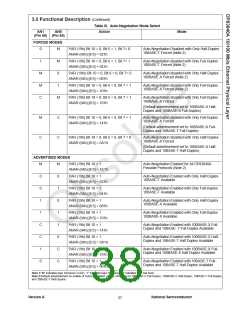
3.0 Functional Description (Continued)
3.9 IEEE 802.3u AUTO-NEGOTIATION
VCC
The Auto-Negotiation function provides a mechanism for
exchanging configuration information between two ends of
a link segment and automatically selecting the highest
performance mode of operation supported by both devices.
Fast Link Pulses (FLP) Bursts provide the signaling used to
communicate Auto-Negotiation abilities between two
devices at each end of a link segment. For further detail
regarding Auto-Negotiation, refer to clause 28 of the IEEE
802.3u specification. The DP83840A supports four
different Ethernet protocols (10 Mb/s Half Duplex, 10 Mb/s
Full Duplex, 100 Mb/s Half Duplex, and 100 Mb/s Full
Duplex), so the inclusion of Auto-Negotiation ensures that
the highest performance protocol will be selected based on
the ability of the Link Partner. The Auto-Negotiation
function within the DP83840A can be controlled either by
internal register access or by use of the AN1 and AN0 (pins
46 and 95.)
VH
-
A
B
R
+
OUT
VIN
-
R
+
VL
GND
VIN
A
B
L
OUT
L
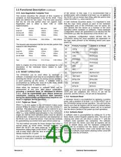
3.9.1 Auto-Negotiation Pin Control
0V
L
L
The state of AN0 and AN1 determines whether the
DP83840A is forced into a specific mode or Auto-
Negotiation will advertise a specific ability or set of abilities
as given in Table III. Pins AN0 and AN1 are implemented
as quad-state control pins which are configured by
connecting them to VCC, GND, a continuous 25 MHz
clock, or by leaving them unconnected (refer to Figure 18)
and allow configuration options to be selected without
requiring internal register access. Due to the nature of
these inputs, using the clock option requires the use of a
CMOS logic level clock signal (high within 10% of VCC).
Additionally, it is recommended that, when using the clock
option, the continuous 25MHz clock be buffered before
driving either AN0 or AN1 as these inputs are not typical
high impedance CMOS input structures.
VCC /2
VCC
H
M
H
H
H
C
25 MHz 25 MHz 25 MHz
FIGURE 19. Quad-State Pin Control
AN1 pins do not affect the contents of the BMCR and
cannot be used by software to obtain status of the mode
selected. The status of Auto-Negotiation Enable, Duplex
mode, and Speed Indication independent of configuration
via Auto-Negotiation, software, or AN0 and AN1 may be
obtained by reading bits 10, 7, and 6 (respectively) of the
PAR (address 19h.)
The state of AN0 and AN1 determines the state of PAR bits
6, 7, & 10 as well as ANAR bits 5 to 8 upon power-up or
hardware reset.
Bits 6 and 7 of the PAR are valid if Auto-Negotiation is
disabled or after Auto-Negotiation is complete.
Upon software reset the DP83840A uses default register
values, which enables Auto-Negotiation and advertises the
full set of abilities (10 Mb/s Half Duplex, 10 Mb/s Full
Duplex, 100 Mb/s Half Duplex, and 100 Mb/s Full Duplex)
unless subsequent software accesses modify the mode.
The contents of the ANLPAR register are used to
automatically configure to the highest performance
protocol between the local and far-end ports. Software can
determine which mode has been configured by Auto-
Negotiation by comparing the contents of the ANAR and
ANLPAR registers and then selecting the technology
whose bit is set in both the ANAR and ANLPAR of highest
priority relative to the following list.
The status Auto-Negotiation as a function of hardware
configuration via the AN0 and AN1 pins is not reflected in
the BMCR. It is reflected in bit 10 of the Physical Address
Register (see 3.9.2 Auto-Negotiation Register Control for
details.)
Auto-Negotiation Priority Resolution:
1. 100BASE-TX Full Duplex (Highest Priority)
2. 100BASE-TX Half Duplex
The Auto-Negotiation function selected at power-up or
hardware reset can be changed at any time by writing to
the Basic Mode Control Register (BMCR) at address 00h.
3. 10BASE-T Full Duplex
3.9.2 Auto-Negotiation Register Control
4. 10BASE-T Half Duplex (Lowest Priority)
When Auto-Negotiation is enabled, the DP83840A
transmits the abilities programmed into the Auto-
Negotiation Advertisement Register (ANAR) at address
04h via FLP Bursts. Any combination of 10 Mb/s, 100 Mb/s,
Half-Duplex, and Full Duplex modes may be selected. The
default setting of bits 5 to 8 in the ANAR and bits 10, 7, & 6
in the PAR (address 19h) are determined at power-up or
hard reset by the state of the AN0 and AN1 pins (see 3.9.1
Auto-Negotiation Pin Control.)
The Basic Mode Control Register (BMCR) at address 00h
provides control of enabling, disabling, and restarting of the
Auto-Negotiation function. When Auto-Negotiation is
disabled the Speed Selection bit in the BCMR (bit 13,
register address 00h) controls switching between 10 Mb/s
or 100 Mb/s operation, while the Duplex Mode bit (bit 8,
register address 00h) controls switching between full
duplex operation and half duplex operation. The Speed
Selection and Duplex Mode bits have no effect on the
mode of operation when the Auto-Negotiation Enable bit
(bit 12, register address 00h) is set.
The BMCR provides software with a mechanism to control
the operation of the DP83840A. However, the AN0 and
Version A
National Semiconductor
36

 TI [ TEXAS INSTRUMENTS ]