3.0 Functional Description (Continued)
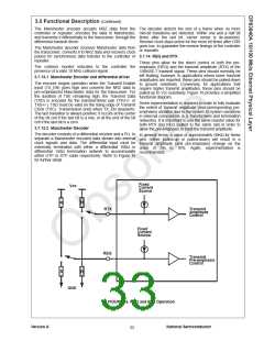
3.7.15 Typical Node Application
3.8 IEEE 1149.1 CONTROLLER
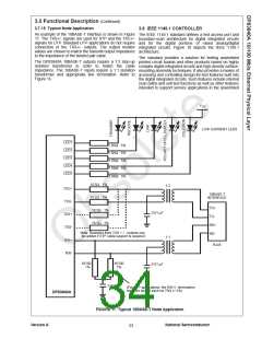
An example of the 10BASE-T interface is shown in Figure
17. The TXS+/- signals are used for STP and the TXU+/-
signals for UTP. Standard UTP applications do not require
connection of the TXS+/- outputs. The output resistor
values are chosen to match the transmit output impedance
to the impedance of the twisted pair cable.
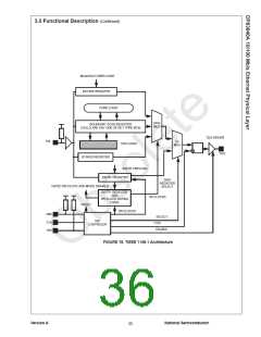
The IEEE 1149.1 standard defines a test access port and
boundary-scan architecture for digital integrated circuits
and for the digital portions of mixed analog/digital
integrated circuits. Figure 18 depicts the IEEE 1149.1
architecture.
The standard provides a solution for testing assembled
printed circuit boards and other products based on highly
complex digital integrated circuits and high-density surface-
mounting assembly techniques. It also provides a means of
accessing and controlling design-for-test features built into
the digital integrated circuits. Such features include internal
scan paths and self-test functions as well as other features
intended to support service applications in the assembled
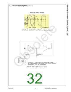
The DP83840A 10BASE-T outputs require a 1:2 step-up
isolation transformer in order to match the cable
impedance. The 10BASE-T inputs require a 1:1 isolation
transformer and appropriate line termination. Refer to
Figure 16.
V
CC
LOW CURRENT LEDS
LED1
1.5KΩ 5%
LED2
1.5KΩ 5%
LED3
1.5KΩ 5%
LED4
1.5KΩ 5%
LED5
1.5KΩ 5%
10.5Ω 1%
1:2
TXU+
10BASE-T
INTERFACE
10.5Ω 1%
TXU-
TD+
TD-
16.5Ω 1%
0.01 µF
TXS+
16.5Ω 1%
RD+
RD-
TXS-
Note: Resistors from TXS + / - outputs can
be added if STP cable support is required.
RXI+
1:1
RJ45
RXI-
49.9Ω
1%
49.9Ω
1%
0.01 µF
0.01 µF
(For STP applications, the RXI+/- termination
resistors should each be 75Ω +/-1%)
DP83840A
FIGURE 17. Typical 10BASE-T Node Application
Version A
National Semiconductor
33

 TI [ TEXAS INSTRUMENTS ]