3.0 Functional Description (Continued)
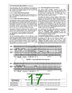
the second bit of Turnaround and follows this with the With bit 10 in the BMCR set to one the DP83840A does not
required data. Figure 2 shows the timing relationship respond to packet data present at TXD[3:0], TX_EN, and
between MDC and the MDIO as driven/received by the TX_ER inputs and presents a high impedance on the
Station Management Entity (STA) and the DP83840A TX_CLK, RX_CLK, RX_DV, RX_ER, RXD[3:0], COL, and
(PHY) for a typical register read access.
CRS outputs. The CLK_25M output remains active and the
DP83840A will continue to respond to all management
transactions.
For write transactions, the station management entity
writes data to an addressed DP83840A eliminating the
requirement for MDIO Turnaround. The Turnaround time is While in Isolate mode, the TD +/-, TXU +/-, and TXS +/-
filled by the management entity inserting <10> for these outputs will not transmit packet data. However, the
two bits. Figure 3 shows the timing relationship for a typical DP83840A will default to 100 Mb/s mode and source
MII register write access.
100BASE-X Idles during the Isolate condition. Data
present on the RD +/- and RXI +/- inputs is ignored and the
link will be forced to disable.
3.2.1.1 Preamble Suppression
The DP83840A supports a Preamble Suppression mode
as indicated by a one in bit 6 of the Basic Mode Status
Register (BMSR, address 01h.) If the station management
entity (i.e. MAC or other management controller)
determines that all PHYs in the system support Preamble
Suppression by returning a one in this bit, then the station
management entity need not generate preamble for each
management transaction.
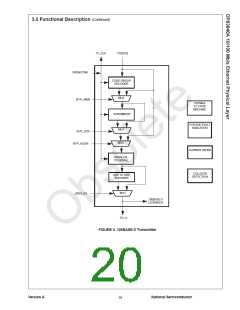
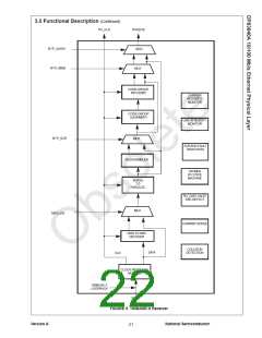
3.3 100BASE-X TRANSMITTER
The 100BASE-X transmitter consists of functional blocks
which convert synchronous 4-bit nibble data, as provided
by the MII, to a scrambled 125 Mb/s serial data stream.
This data stream may be routed either to a twisted pair
PMD such as the DP83223 TWISTER for 100BASE-TX
signaling, or to an optical PMD for 100BASE-FX
applications. The block diagram in Figure 4 provides an
overview of each functional block within the 100BASE-X
transmit section.
The DP83840A requires a single initialization sequence of
32 bits of preamble following power-up/hardware reset.
This requirement is generally met by the mandatory pull-up
resistor on MDIO or the management access made to
determine whether Preamble Suppression is supported.
The Transmitter section consists of the following functional
blocks:
While the DP83840A will respond to management
accesses without preamble, a minimum of one idle bit
between management transactions is required as specified
in IEEE 802.3u.
• code-group Encoder and Injection block (bypass option)
• Scrambler block (bypass option)
• NRZ to NRZI encoder block (bypass option)
The bypass option for each of the functional blocks within
the 100BASE-X transmitter provides flexibility for
applications such as 100 Mb/s repeaters where data
conversion is not always required.
3.2.2 PHY Address Sensing
The DP83840A can be set to respond to any of the
possible 32 PHY addresses. Each DP83840A connected
to a common serial MII must have a unique address. It
should be noted that while an address selection of all zeros
<00000> will result in PHY Isolate mode, this will not effect
serial management access.
3.3.1 100 Mb/s Transmit State Machine
The DP83840A implements the 100BASE-X transmit state
machine diagram as given in the IEEE 802.3u Standard,
Clause 24.
The DP83840A provides five PHY address pins, the state
of which are latched into the PHY Address Register (PAR)
at system power-up/reset. These pins are described in
Section 2.8. For further detail relating to the latch-in timing
requirements of the PHY Address pins, as well as the other
hardware configuration pins, refer to section 3.10.
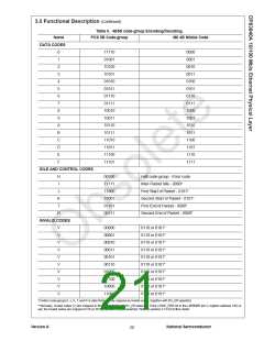
3.3.2 Code-group Encoding and Injection
The code-group encoder converts 4 bit (4B) nibble data
generated by the MAC into 5 bit (5B) code-groups for
transmission. This conversion is required to allow control
data to be combined with packet data code-groups. Refer
to Table II for 4B to 5B code-group mapping details.
3.2.3 MII Management
The code-group encoder substitutes the first 8 bits of the
MAC preamble with a J/K code-group pair (11000 10001).
The code-group encoder continues to replace subsequent
4Bdata with corresponding 5B code-groups. At the end of
the transmit packet, upon the deassertion of Transmit
Enable signal from the MAC or Repeater, the code-group
encoder injects the T/R code-group pair (01101 00111)
indicating end of frame.
The MII may be used to connect PHY devices to MAC or
repeater devices in 10/100 Mb/s systems.
The management interface of the MII allows the
configuration and control of multiple PHY devices, the
gathering of status and error information, and the
determination of the type and abilities of the attached
PHY(s).
3.2.4 MII Isolate Mode
After the T/R code-group pair, the code-group encoder
continuously injects IDLEs into the transmit data stream
until the next transmit packet is detected (reassertion of
Transmit Enable).
A 100BASE-X PHY connected to the mechanical MII
interface specified in IEEE 802.3u is required to have a
default value of one in bit 10 of the Basic Mode Control
Register (BMCR, address 00h.) The DP83840A will set this
bit to one if the PHY Address is set to 00000 upon power-
up/hardware reset. Otherwise, the DP83840A will set this
bit to zero upon power-up/hardware reset.
3.3.3 Scrambler
The scrambler is required to control the radiated emissions
at the media connector and on the twisted pair cable (for
Version A
National Semiconductor
17

 TI [ TEXAS INSTRUMENTS ]