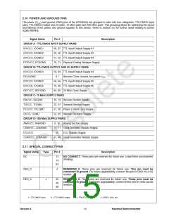
3.0 Functional Description (Continued)
100BASE-TX applications). By scrambling the data, the • Far End Fault Indication block
total energy launched onto the cable is randomly
distributed over a wide frequency range. Without the
scrambler, energy levels at the PMD and on the cable
would peak beyond FCC limitations at frequencies related
to repeating 5B sequences (i.e., continuous transmission
of IDLEs).
• Link Integrity Monitor block
• Carrier Integrity Monitor Block
The bypass option for each of the functional blocks within
the 100BASE-X receiver provides flexibility for applications
such as 100 Mb/s repeaters where data conversion is not
always required.
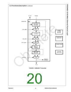
The scrambler is configured as a closed loop linear
feedback shift register (LFSR) with an 11-bit polynomial.
The output of the closed loop LFSR is combined with the
NRZ 5B data from the code-group encoder via an X-OR
logic function. The result is a scrambled data stream with
sufficient randomization to decrease radiated emissions at
certain frequencies by as much as 20 dB. The DP83840A
uses the PHYID as determined by the PHYAD [4:0] pins to
set a unique seed value for the scrambler so that the total
energy produced by a multi-PHY application (i.e. repeater)
distributes the energy across the spectrum and reduces
overall EMI.
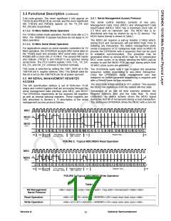
3.4.1 Clock Recovery
The Clock Recovery Module (CRM) accepts 125 Mb/s
scrambled or unscrambled NRZI data from an external
twisted pair or fiber PMD receiver. The CRM locks onto the
125 Mb/s data stream and extracts a 125 MHz reference
clock. The extracted and synchronized clock and data are
used as required by the synchronous receive operations as
generally depicted in Figure 5.
The CRM is implemented using an advanced digital Phase
Locked Loop (PLL) architecture that replaces sensitive
analog circuits. Using digital PLL circuitry allows the
DP83840A to be manufactured and specified to tighter
tolerances.
3.3.4 NRZ to NRZI Encoder
After the transmit data stream has been scrambled and
serialized, the data must be NRZI encoded in order to
comply with the TP-PMD standard for 100BASE-TX
transmission over Category-5 un-shielded twisted pair
cable. Normal operation for both twisted pair and fiber
applications requires that this encoder remain engaged.
This encoder should only be bypassed for system testing
and or debug.
3.4.2 NRZI to NRZ
In a typical application the NRZI to NRZ decoder is
required in order to present NRZ formatted data to the
descrambler (or to the code-group alignment block if the
descrambler is bypassed).
The receive data stream, as recovered by the PMD
receiver, is in NRZI format, therefore the data must be
decoded to NRZ before further processing.
3.3.5 TX_ER
Assertion of the TX_ER input while the TX_EN input is also
asserted will cause the DP83840A to substitute HALT
code-groups for the 5B data present at TXD[3:0]. However,
the SSD (/J/K/) and ESD (/T/R/) will not be substituted with
Halt code-groups. As a result, the assertion of TX_ER
while TX_EN is asserted will result in a frame properly
encapsulated with the /J/K/ and /T/R/ delimiters which
contains HALT code-groups in place of the data code-
groups.
3.4.3 Descrambler
A 5-bit parallel (code-group wide) descrambler is used to
de- scramble the receive NRZ data. To reverse the data
scrambling process, the descrambler has to generate an
identical data scrambling sequence (N) in order to recover
the original unscrambled data (UD) from the scrambled
data (SD) as represented in the equations:
SD= (UD N)
UD= (SD N)
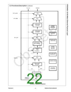
3.4 100BASE-X RECEIVER
The 100BASE-X receiver consists of several functional
blocks which are required to recover and condition the 125
Mb/s receive data stream as specified by the IEEE 802.3u
Standard. The 125 Mb/s receive data stream may originate
from a twisted pair transceiver such as the DP83223
TWISTER in a 100BASE-TX application. Alternatively, the
receive data stream may be generated by an optical
receiver as in a 100BASE-FX application. The block
diagram in Figure 5 provides an overview of each
functional block within the 100BASE-X receive section.
Synchronization of the descrambler to the original
scrambling sequence (N) is achieved based on the
knowledge that the incoming scrambled data stream
consists of scrambled IDLE data. After the descrambler
has recognized 16 consecutive IDLE code-groups, where
an IDLE code-group in 5B NRZ is equal to five consecutive
ones (11111), it will synchronize to the receive data stream
and generate unscrambled data in the form of unaligned
5B code-groups.
In order to maintain synchronization, the descrambler must
continuously monitor the validity of the unscrambled data
that it generates. To ensure this, a line state monitor and a
hold timer are used to constantly monitor the
synchronization status. Upon synchronization of the
descrambler the hold timer starts a 722µs countdown.
Upon detection of sufficient IDLE code-groups within the
722µs period, the hold timer will reset and begin a new
countdown. This monitoring operation will continue
indefinitely given a properly operating network connection
with good signal integrity. If the line state monitor does not
recognize sufficient unscrambled IDLE code-groups within
the 722µs period, the entire descrambler will be forced out
The Receiver block consists of the following functional
blocks:
• Clock Recovery block
• NRZI to NRZ decoder block (bypass option)
• Descrambler block (bypass option)
• code-group Alignment block (bypass option)
• 5B/4B code-group Decoder block (bypass option)
• Collision Detect block
• Carrier Sense block
• 100 Mb/s Receive State Machine
Version A
National Semiconductor
18

 TI [ TEXAS INSTRUMENTS ]