DM385, DM388
SPRS821D –MARCH 2013–REVISED DECEMBER 2013
8.3 Audio Tracking Logic (ATL)
8.3.1 Overview
www.ti.com
The device contains four ATL modules that can be used for asynchronous sample rate conversion of
audio. The ATL calculates the error between two time bases, such as audio syncs, and optionally
generates an averaged clock using cycle stealing via software.
For more detailed information on the ATL peripheral, see the Audio Tracking Logic (ATL) chapter of the
device-specific Technical Reference Manual.
8.3.2 ATL Peripheral Registers
This ATL peripheral registers are described in the device-specific Technical Reference Manual (TRM).
Each register is documented as an offset from a base address for the peripheral. The base addresses for
all of the peripherals are in the device memory map (see Section 2.10).
8.3.3 ATL Electrical Data/Timing
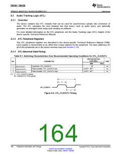
Table 8-1. Switching Characteristics Over Recommended Operating Conditions for ATL_CLKOUTx
OPP100/OPP120/
Turbo/Nitro
NO.
PARAMETER
UNIT
MIN
MAX
1
2
3
tc(ATLCLKOUT)
tw(ATLCLKOUTL)
tw(ATLCLKOUTH)
Cycle time, ATL_CLKOUTx
20
ns
ns
ns
Pulse Duration, ATL_CLKOUTx low
Pulse Duration, ATL_CLKOUTx high
0.45*P - M(1)
0.45*P - M(1)
(1) P = ATL_CLKOUTx period.
M = internal ATL PCLK period.
1
2
ATL_CLKOUTx
3
Figure 8-4. ATL_CLKOUTx Timing
164
Peripheral Information and Timings
Copyright © 2013, Texas Instruments Incorporated
Submit Documentation Feedback
Product Folder Links: DM385 DM388

 TI [ TEXAS INSTRUMENTS ]