DM385, DM388
www.ti.com
SPRS821D –MARCH 2013–REVISED DECEMBER 2013
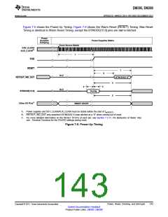
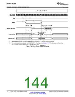
Figure 7-5 shows the Power-Up Timing. Figure 7-6 shows the Warm Reset (RESET) Timing. Max Reset
Timing is identical to Warm Reset Timing, except the BTMODE[15:0] pins are not re-latched.
Power
Supplies
Ramping
Power Supplies Stable
Clock Source Stable
DEV_CLKIN/
AUX_CLKIN(A)
1
POR
RESET
7
9
Hi-Z
Hi-Z
BTMODE[11](B)
RSTOUT_WD_OUT
5
2
3
BTMODE[15:0]
Other I/O Pins(C)
Config
5
RESET STATE
A. Power supplies and DEV_CLKIN/AUX_CLKIN must be stable before the start of tw(RESET)
.
B. RSTOUT_WD_OUT only asserted if BTMODE[11] was latched as a "0" when coming out of reset.
C. For more detailed information on the RESET STATE of each pin, see Section 7.3.17, Pin Behaviors at Reset. Also
see , Terminal Functions for the IPU/IPD settings during reset.
Figure 7-5. Power-Up Timing
Copyright © 2013, Texas Instruments Incorporated
Power, Reset, Clocking, and Interrupts
143
Submit Documentation Feedback
Product Folder Links: DM385 DM388

 TI [ TEXAS INSTRUMENTS ]