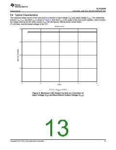
DLPA2000
www.ti.com.cn
ZHCSCO5B –JUNE 2014–REVISED FEBRUARY 2018
Feature Description (continued)
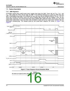
Fault Condition
5 ms (min)
System Power
(VINx)
PROJ_ON
DMD_EN
in register 0x01h
V2V5
Stop Regulating
VBIAS
VBIAS Delay
VBIAS
Pad DMD_EN
by DPP through
VOFS
VOFS
Delay
SPI write
VRST
VRST Delay
10 ms
DMD
initialization
by DPP
≤ 10 ms
145 ms
Stop Regulating
VRST
≥ 10 ms
VCORE
LS_OUT (1.8V)
VLED
INTZ
Startup DPP
RESETZ
RESETZ Delay
STANDBY
ACTIVE1
OFF
STANDBY
ACTIVE2
STATE
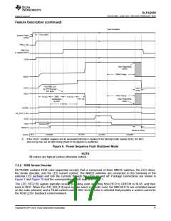
A. If the FAULT condition happens and its associated interrupt is masked in the interrupt mask register (0Dh), the INTZ
does not go low, but all other timing shown in the diagram is unaffected.
Figure 6. Power Sequence Fault Shutdown Mode
NOTE
All values are typical (unless otherwise noted).
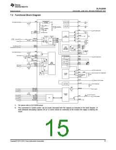
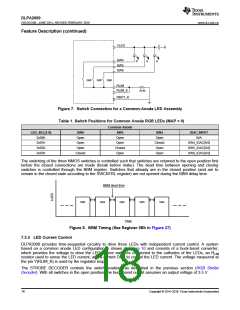
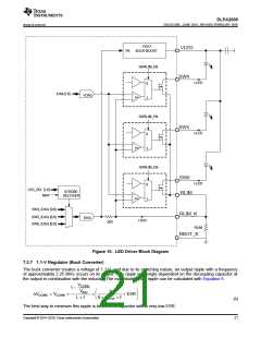
7.3.2 RGB Strobe Decoder
DLPA2000 contains RGB color-sequential circuitry that is composed of three NMOS switches, the LED driver,
the strobe decoder, and the LED current control. The NMOS switches are connected to the terminals of the
external LED package and turn the currents through the LEDs on and off. Package connections are shown in
Figure 7 and Figure 10 and the corresponding switch map is in Table 1.
The LED_SEL[1:0] signals typically receive a rotating code switching from RED to GREEN to BLUE and then
back to RED. When the LED_SEL[1:0] input signals select a specific color, the NMOSFETs are controlled based
on the color selected, and a 10-bit current control DAC for this color is selected that provides a control current to
the RGB LEDs' feedback control network.
Copyright © 2014–2018, Texas Instruments Incorporated
17

 TI [ TEXAS INSTRUMENTS ]