CC1110Fx / CC1111Fx
0xFF
0x00
OVFIF = 1
OVFIF = 1
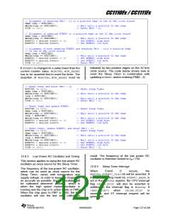
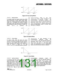
Figure 35: Free-running Mode
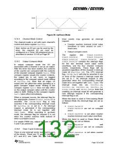
12.9.3.1 Modulo Mode
TIMIF.TxOVFIF
IRCON.TxIF flag is only asserted if the
corresponding interrupt mask bit
TxCTL.OVFIM is set. An interrupt request is
generated when both TxCTL.OVFIM and
IEN1.TxENare set to 1. Modulo mode can be
used for applications where a period other
than 0xFF is required.
flag
is
set.
The
In modulo mode the counter starts from 0x00
and increments at each active clock edge.
When the counter reaches the terminal count
value TxCC0 (overflow), the counter is loaded
with 0x00 on the next timer tick and continues
incrementing its value as shown in Figure 36.
When
TxCC0
is
reached,
the
TxCC0
0x00
OVFIF = 1
OVFIF = 1
Figure 36: Modulo Mode
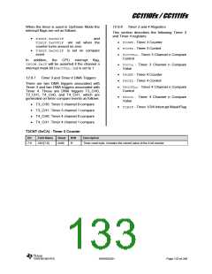
12.9.3.2 Down Mode
IRCON.TxIF
corresponding
is only asserted if the
interrupt mask bit
In down mode, after the timer has been
started, the counter is loaded with the contents
in TxCC0. The counter then counts down to
0x00 (terminal count value) and remains at
0x00 as shown in Figure 37. The flag
TIMIF.TxOVFIFis set when 0x00 is reached.
TxCTL.OVFIM is set. An interrupt request is
generated when both TxCTL.OVFIM and
IEN1.TxEN are set to 1. The timer down
mode can generally be used in applications
where an event timeout interval is required.
TxCC0
0x00
OVFIF = 1
Figure 37: Down Mode
corresponding
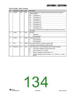
12.9.3.3 Up/Down Mode
interrupt
mask
bit
TxCTL.OVFIM is set. An interrupt request is
generated when both TxCTL.OVFIM and
IEN1.TxEN are set to 1. The up/down mode
can be used when symmetrical output pulses
are required with a period other than 0xFF,
and therefore allows implementation of centre-
aligned PWM output applications.
In up/down mode the counter starts from 0x00
and increments at each active clock edge.
When the counter value matches the terminal
count value TxCC0, the counter counts down
until 0x00 is reached and it starts counting up
again as shown in Figure 38. When 0x00 is
reached, the TIMIF.TxOVFIF flag is set. The
IRCON.TxIF flag is only asserted if the
SWRS033H
Page 131 of 246

 TI [ TEXAS INSTRUMENTS ]