CC1110Fx / CC1111Fx
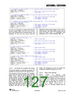
// Alignment of entering PM{0 – 2} to a positive edge on the 32 kHz clock source
char temp = WORTIME0;
while(temp == WORTIME0);
PCON |= 0x01;
// Wait until a positive 32 kHz edge
// Enter PM{0 – 2}
// Alignment of updating EVENT0 to a positive edge on the 32 kHz clock source
char temp = WORTIME0;
while(temp == WORTIME0);
WOREVT1 = desired event0 >> 8;
WOREVT0 = desired event0;
// Wait until a positive 32 kHz edge
// Set EVENT0, high byte
// Set EVENT0, low byte
// Alignment of both updating EVENT0 and entering PM{0 - 2}to a positive edge
// on the 32 kHz clock source
char temp = WORTIME0;
while(temp == WORTIME0);
WOREVT1 = desired event0 >> 8;
WOREVT0 = desired event0;
PCON |= 0x01;
// Wait until a positive 32 kHz edge
// Set EVENT0, high byte
// Set EVENT0, low byte
// Enter PM{0 – 2}
followed by two positive edges on the 32 kHz
clock source. The code below shows how to
reset the Sleep Timer in combination with
updating EVENT0and/or entering PM{0 - 2}.
If EVENT0is changed to a value lower than the
current counter value, WORCTRL.WOR_RESET
has to be asserted first to reset the timer. The
assertion of WORCTRL.WOR_RESET must be
// Reset timer and enter PM{0 – 2}
WORCTRL |= 0x04;
// Reset Sleep Timer
// Wait until a positive 32 kHz edge
char temp = WORTIME0;
while(temp == WORTIME0);
temp = WORTIME0;
while(temp == WORTIME0);
PCON |= 0x01;
// Wait until a positive 32 kHz edge
// Enter PM{0 – 2}
// Reset timer and update EVENT0
WORCTRL |= 0x04;
// Reset Sleep Timer
char temp = WORTIME0;
while(temp == WORTIME0);
// Wait until a positive 32 kHz edge
temp = WORTIME0;
while(temp == WORTIME0);
WOREVT1 = desired event0 >> 8;
WOREVT0 = desired event0;
// Wait until a positive 32 kHz edge
// Set EVENT0, high byte
// Set EVENT0, low byte
// Reset timer, update EVENT0, and enter PM{0 – 2}
WORCTRL |= 0x04;
// Reset Sleep Timer
char temp = WORTIME0;
while(temp == WORTIME0);
temp = WORTIME0;
while(temp == WORTIME0);
WOREVT1 = desired event0 >> 8;
WOREVT0 = desired event0;
PCON |= 0x01;
// Wait until a positive 32 kHz edge
// Wait until a positive 32 kHz edge
// Set EVENT0, high byte
// Set EVENT0, low byte
// Enter PM{0 – 2}
result. The frequency of the low power RC
oscillator is therefore locked to fref / 750.
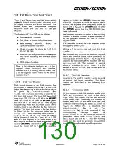
12.8.3
Low Power RC Oscillator and Timing
This section applies to using the low power RC
oscillator as clock source for the Sleep Timer.
12.8.4
Sleep Timer Interrupt
Event occurs,
The frequency of the low-power RC oscillator,
which can be used as clock source for the
Sleep Timer, varies with temperature and
supply voltage. In order to keep the frequency
as accurate as possible, the RC oscillator will
be calibrated whenever possible, which is
when the high speed crystal oscillator is
running and the chip is in active mode or PM0.
When the chip goes to PM1 or PM2, the RC
oscillator will use the last valid calibration
When
0
the
WORIRQ.EVENT0_FLAGbit will be asserted. If
the corresponding mask bit, EVENT0_MASK, is
set in the WORIRQ register, the CPU interrupt
flag IRCON.STIF will also be asserted in
addition to the interrupt flag in WORIRQ. If
IEN0.STIE=1
when
IRCON.STIF
is
asserted, and ST interrupt request will be
generated.
SWRS033H
Page 127 of 246

 TI [ TEXAS INSTRUMENTS ]