CC1110Fx / CC1111Fx
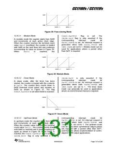
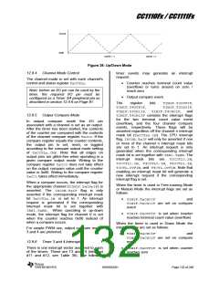
TxCC0
0x00
OVFIF = 1
OVFIF = 1
Figure 38: Up/Down Mode
12.9.4
Channel Mode Control
timer events may generate an interrupt
request:
The channel mode is set with each channel’s
control and status register TxCCTLn.
Counter reaches terminal count value
(overflow) or turns around on zero /
reach zero
Note: before an I/O pin can be used by the
timer, the required I/O pin must be
configured as a Timer 3/4 peripheral pin as
described in section 12.4.6 on Page 91.
Output compare event
The
register
TIMIF.T4OVFIF,
bits
TIMIF.T3OVFIF,
TIMIF.T3CH0IF,
TIMIF.T3CH1IF, TIMIF.T4CH0IF, and
TIMIF.T4CH1IF contains the interrupt flags
for the two terminal count value event
(overflow), and the four channel compare
events, respectively. These flags will be
asserted regardless off the channel n interrupt
mask bit (TxCCTLn.IM). The CPU interrupt
flag, IRCON.TxIF will only be asserted if one
or more of the channel n interrupt mask bits
are set to 1. An interrupt request is only
generated when the corresponding interrupt
mask bit is set together with IEN1.TxEN. The
interrupt mask bits are T3CCTL0.IM,
T3CCTL1.IM, T4CCTL0.IM, T4CCTL1.IM,
T3CTL.OVFIM, and T4CTL.OVFIM. Note that
enabling an interrupt mask bit will generate a
new interrupt request if the corresponding
interrupt flag is set.
12.9.5
Output Compare Mode
In output compare mode the I/O pin
associated with a channel is set as an output.
After the timer has been started, the contents
of the counter are compared with the contents
of the channel compare register TxCCn. If the
compare register equals the counter contents,
the output pin is set, reset, or toggled
according to the compare output mode setting
of TxCCTLn.CMP. Note that all edges on
output pins are glitch-free when operating in a
given compare output mode. Writing to the
compare register TxCC0 does not take effect
on the output compare value until the counter
value is 0x00. Writing to the compare register
TxCC1takes effect immediately.
When a compare occurs, the interrupt flag for
the appropriate channel (TIMIF.TxCHnIF) is
asserted. The IRCON.TxIF flag is only
asserted if the corresponding interrupt mask
bit TxCCTLn.IM is set to 1. An interrupt
request is generated if the corresponding
interrupt mask bit is set together with
IEN1.TxEN. When operating in up-down
mode, the interrupt flag for channel 0 is set
when the counter reaches 0x00 instead of
when a compare occurs.
When the timer is used in Free-running Mode
or Modulo Mode the interrupt flags are set as
follows:
TIMIF.TxCH0IF
and
TIMIF.TxCH1IF are set on compare
event
TIMIF.TxOVFIF is set when counter
reaches terminal count value (overflow)
When the timer is used in Down Mode the
interrupt flags are set as follows:
For simple PWM use, output compare modes
3 and 4 are preferred.
TIMIF.TxCH0IF
and
TIMIF.TxCH1IF are set on compare
12.9.6
Timer 3 and 4 Interrupts
event
There is one interrupt vector assigned to each
of the timers. These are T3 and T4 (interrupt
#11 and #12, see Table 39). The following
TIMIF.TxOVFIF is set when counter
reaches zero
SWRS033H
Page 132 of 246

 TI [ TEXAS INSTRUMENTS ]