CC1110Fx / CC1111Fx
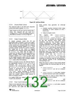
When the timer is used in Up/Down Mode the
interrupt flags are set as follows:
12.9.8
Timer 3 and 4 Registers
This section describes the following Timer 3
and Timer 4 registers:
TIMIF.TxCH0IF
and
T3CNT- Timer 3 Counter
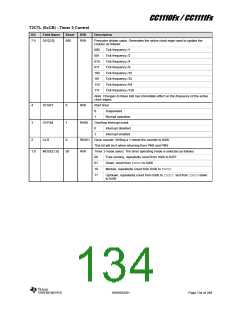
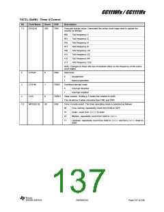
T3CTL- Timer 3 Control
TIMIF.TxOVFIF are set when the
counter turns around on zero
TIMIF.TxCH1IF is set on compare
event
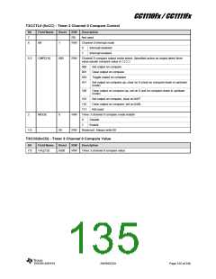
T3CCTLn- Timer 3 Channel n Compare
Control
In addition, the CPU interrupt flag,
IRCON.TxIF will be asserted if the channel n
interrupt mask bit (TxCCTLn.IM) is set to 1.
T3CCn - Timer 3 Channel n Compare
Value
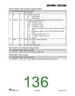
T4CNT- Timer 4 Counter
T4CTL- Timer 4 Control
12.9.7
Timer 3 and Timer 4 DMA Triggers
There are two DMA triggers associated with
Timer 3 and two DMA triggers associated with
Timer 4. These are DMA triggers T3_CH0,
T3_CH1, T4_CH0, and T4_CH1, which are
generated on timer compare events as follows:
T4CCTLn- Timer 4 Channel n Compare
Control
T4CCn - Timer 4 Channel n Compare
Value
T3_CH0: Timer 3 channel 0 compare
T3_CH1: Timer 3 channel 1 compare
T4_CH0: Timer 4 channel 0 compare
T4_CH1: Timer 4 channel 1 compare
TIMIF- Timer 1/3/4 Interrupt Mask/Flag
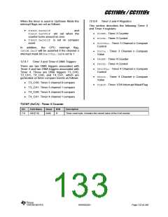
T3CNT (0xCA) - Timer 3 Counter
Bit
Field Name
Reset
R/W
Description
Timer count byte. Contains the current value of the 8-bit counter
7:0
CNT[7:0]
0x00
R
SWRS033H
Page 133 of 246

 TI [ TEXAS INSTRUMENTS ]