bq24707
bq24707A
SLUSA78B –JULY 2010–REVISED MARCH 2011
www.ti.com
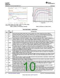
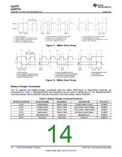
Figure 17. SMBus Write Timing
A
B
C
D
E
F
G
H
I
J
K
tLOW tHIGH
A
= START CONDITION
E = SLAVE PULLS SMBDATA LINE LOW
I = ACKNOWLEDGE CLOCK PULSE
J = STOP CONDITION
B = MSB OF ADDRESS CLOCKED INTO SLAVE
C = LSB OF ADDRESS CLOCKED INTO SLAVE
D = R/W BIT CLOCKED INTO SLAVE
F = ACKNOWLEDGE BIT CLOCKED INTO MASTER
G = MSB OF DATA CLOCKED INTO MASTER
H = LSB OF DATA CLOCKED INTO MASTER
K = NEW START CONDITION
Figure 18. SMBus Read Timing
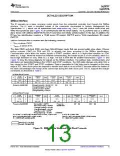
Battery-Charger Commands
The IC supports six battery-charger commands that use either Write-Word or Read-Word protocols, as
summarized in Table 2. ManufacturerID() and DeviceID() can be used to identify the IC. The ManufacturerID()
command always returns 0x0040H and the DeviceID() command always returns 0x000AH.
Table 2. Battery Charger Command Summary
REGISTER ADDRESS
0x12H
REGISTER NAME
ChargeOption()
ChargeCurrent()
ChargeVoltage()
InputCurrent()
READ/WRITE
Read or Write
Read or Write
Read or Write
Read or Write
Read Only
DESCRIPTION
Charger Options Control
7-Bit Charge Current Setting
11-Bit Charge Voltage Setting
6-Bit Input Current Setting
Manufacturer ID
POR STATE
0x7904H
0x0000H
0x0000H
0x1000H
0x0040H
0x000AH
0x14H
0x15H
0x3FH
0XFEH
ManufacturerID()
DeviceID()
0xFFH
Read Only
Device ID
14
Submit Documentation Feedback
© 2010–2011, Texas Instruments Incorporated
Product Folder Link(s): bq24707 bq24707A

 TI [ TEXAS INSTRUMENTS ]