bq24707
bq24707A
SLUSA78B –JULY 2010–REVISED MARCH 2011
www.ti.com
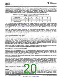
can also be used. With a larger sense resistor comes a larger sense voltage, and higher regulation accuracy;
but, at the expense of higher conduction loss. If the current sensing resistor value is too high, it may trig over
current protection threshold due to the current ripple voltage being too high. In such a case either a higher
inductance value or a lower current sensing resistor value should be used to limit the current ripple voltage level.
A current sensing resistor value of no more than 20mΩ is suggested.
To provide secondary protection, the IC has an ILIM pin with which the user can program the maximum allowed
charge current. Internal charge current limit is the lower one between the voltage set by ChargeCurrent(), and
voltage on the ILIM pin. To disable this function, the user can pull ILIM above 1.6V, which is the maximum
charge current regulation limit. The following equation shows the voltage should add on the ILIM pin with respect
to the preferred charge current limit:
V
= 20 × V
(
- VSRN = 20 ´ I
)
´ RSR
ILIM
SRP
CHG
(1)
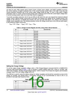
Table 4. Charge Current Register (0x14H), Using 10mΩ Sense Resistor
BIT
0
BIT NAME
DESCRIPTION
–
Not used.
Not used.
Not used.
Not used.
Not used.
Not used.
1
–
2
–
3
–
4
–
5
–
6
Charge Current, DACICHG 0
0 = Adds 0mA of charger current.
1 = Adds 64mA of charger current.
7
8
Charge Current, DACICHG 1
Charge Current, DACICHG 2
Charge Current, DACICHG 3
Charge Current, DACICHG 4
Charge Current, DACICHG 5
Charge Current, DACICHG 6
0 = Adds 0mA of charger current.
1 = Adds 128mA of charger current.
0 = Adds 0mA of charger current.
1 = Adds 256mA of charger current.
9
0 = Adds 0mA of charger current.
1 = Adds 512mA of charger current.
10
11
12
0 = Adds 0mA of charger current.
1 = Adds 1024mA of charger current.
0 = Adds 0mA of charger current.
1 = Adds 2048mA of charger current.
0 = Adds 0mA of charger current.
1 = Adds 4096mA of charger current.
13
14
15
–
–
–
Not used.
Not used.
Not used.
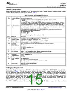
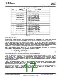
Setting the Charge Voltage
To set the output charge regulation voltage, write a 16bit ChargeVoltage() command (0x15H or 0b00010101)
using the data format listed inTable 5. The IC provides a charge voltage range from 1.024V to 19.200V, with
16mV step resolution. Sending ChargeVoltage() below 1.024V or above 19.2V clears the register and terminates
charging. Upon POR, the charge voltage limit is 0V.
The SRN pin is used to sense the battery voltage for voltage regulation and should be connected as close to the
battery as possible, and directly place a decoupling capacitor (0.1µF recommended) as close to the IC as
possible to decouple high frequency noise.
Table 5. Charge Voltage Register (0x15H)
BIT
0
BIT NAME
DESCRIPTION
-
-
-
-
Not used.
Not used.
Not used.
Not used.
1
2
3
16
Submit Documentation Feedback
© 2010–2011, Texas Instruments Incorporated
Product Folder Link(s): bq24707 bq24707A

 TI [ TEXAS INSTRUMENTS ]