bq24707
bq24707A
www.ti.com
SLUSA78B –JULY 2010–REVISED MARCH 2011
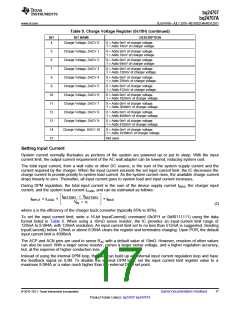
Table 5. Charge Voltage Register (0x15H) (continued)
BIT
BIT NAME
DESCRIPTION
4
Charge Voltage, DACV 0
0 = Adds 0mV of charger voltage.
1 = Adds 16mV of charger voltage.
5
6
Charge Voltage, DACV 1
Charge Voltage, DACV 2
Charge Voltage, DACV 3
Charge Voltage, DACV 4
Charge Voltage, DACV 5
Charge Voltage, DACV 6
Charge Voltage, DACV 7
Charge Voltage, DACV 8
Charge Voltage, DACV 9
Charge Voltage, DACV 10
-
0 = Adds 0mV of charger voltage.
1 = Adds 32mV of charger voltage.
0 = Adds 0mV of charger voltage.
1 = Adds 64mV of charger voltage.
7
0 = Adds 0mV of charger voltage.
1 = Adds 128mV of charger voltage.
8
0 = Adds 0mV of charger voltage.
1 = Adds 256mV of charger voltage.
9
0 = Adds 0mV of charger voltage.
1 = Adds 512mV of charger voltage.
10
11
12
13
14
15
0 = Adds 0mV of charger voltage.
1 = Adds 1024mV of charger voltage.
0 = Adds 0mV of charger voltage.
1 = Adds 2048mV of charger voltage.
0 = Adds 0mV of charger voltage.
1 = Adds 4096mV of charger voltage.
0 = Adds 0mV of charger voltage.
1 = Adds 8192mV of charger voltage.
0 = Adds 0mV of charger voltage.
1 = Adds 16384mV of charger voltage.
Not used.
Setting Input Current
System current normally fluctuates as portions of the system are powered up or put to sleep. With the input
current limit, the output-current requirement of the AC wall adapter can be lowered, reducing system cost.
The total input current, from a wall cube or other DC source, is the sum of the system supply current and the
current required by the charger. When the input current exceeds the set input current limit, the IC decreases the
charge current to provide priority to system load current. As the system current rises, the available charge current
drops linearly to zero. Thereafter, all input current goes to system load and input current increases.
During DPM regulation, the total input current is the sum of the device supply current IBIAS, the charger input
current, and the system load current ILOAD, and can be estimated as follows:
é
ê
ë
ù
ú
û
IBATTERY ´ VBATTERY
I
= ILOAD
+
+ IBIAS
INPUT
V
´ η
IN
(2)
where η is the efficiency of the charger buck converter (typically 85% to 95%).
To set the input current limit, write a 16-bit InputCurrent() command (0x3FH or 0b00111111) using the data
format listed in Table 6. When using a 10mΩ sense resistor, the IC provides an input-current limit range of
128mA to 8.064A, with 128mA resolution. An input current limit set to no less than 512mA is suggested. Sending
InputCurrent() below 128mA or above 8.064A clears the register and terminates charging. Upon POR, the default
input current limit is 4096mA.
The ACP and ACN pins are used to sense RAC with a default value of 10mΩ. However, resistors of other values
can also be used. With a larger sense resistor, comes a larger sense voltage, and a higher regulation accuracy;
but, at the expense of higher conduction loss.
Instead of using the internal DPM loop, the user can build up an external input current regulation loop and have
the feedback signal on ILIM. To disable the internal DPM loop, set the input current limit register value to a
maximum 8.064A or a value much higher than the external DPM set point.
© 2010–2011, Texas Instruments Incorporated
Submit Documentation Feedback
17
Product Folder Link(s): bq24707 bq24707A

 TI [ TEXAS INSTRUMENTS ]