ADS62P49 / ADS62P29
ADS62P48 / ADS62P28
www.ti.com............................................................................................................................................................. SLAS635A–APRIL 2009–REVISED JUNE 2009
39 nH
0.1 mF
0.1 mF
15 W
INP
50 W
25 W
25 W
50 W
0.1 mF
22 pF
50 W
50 W
INM
15 W
0.1 mF
1:1
1:1
VCM
39 nH
S0396-01
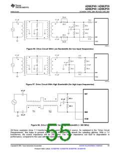
Figure 96. Drive Circuit With Low Bandwidth (for low input frequencies)
0.1 mF
0.1 mF
5 W
INP
25 W
25 W
50 W
0.1 mF
3.3 pF
50 W
INM
5 W
0.1 mF
1:1
1:1
VCM
S0397-01
Figure 97. Drive Circuit With High Bandwidth (for high input frequencies)
0.1mF
INP
25 W
0.1mF
25 W
T1
T2
INM
0.1mF
VCM
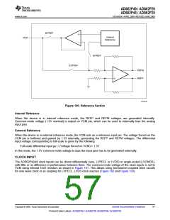
Figure 98. Drive Circuit with Very High Bandwidth (> 300 MHz)
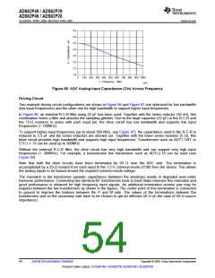
All these examples show 1:1 transformers being used with a 50-Ω source. As explained in the “Drive Circuit
Requirements”, this helps to present a low source impedance to absorb the sampling glitches. With a 1:4
transformer, the source impedance will be 200 ohms. The higher impedance can lead to degradation in
performance, compared to the case with 1:1 transformers.
Copyright © 2009, Texas Instruments Incorporated
Submit Documentation Feedback
55
Product Folder Link(s): ADS62P49 / ADS62P29 ADS62P48 / ADS62P28

 TI [ TEXAS INSTRUMENTS ]