ADS62P49 / ADS62P29
ADS62P48 / ADS62P28
SLAS635A–APRIL 2009–REVISED JUNE 2009............................................................................................................................................................. www.ti.com
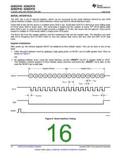
SERIAL INTERFACE
The ADC has a set of internal registers, which can be accessed by the serial interface formed by pins SEN
(Serial interface Enable), SCLK (Serial Interface Clock) and SDATA (Serial Interface Data).
Serial shift of bits into the device is enabled when SEN is low. Serial data SDATA is latched at every falling edge
of SCLK when SEN is active (low). The serial data is loaded into the register at every 16th SCLK falling edge
when SEN is low. In case the word length exceeds a multiple of 16 bits, the excess bits are ignored. Data can be
loaded in multiple of 16-bit words within a single active SEN pulse.
The first 8 bits form the register address and the remaining 8 bits are the register data. The interface can work
with SCLK frequency from 20 MHz down to very low speeds (few Hertz) and also with non-50% SCLK duty
cycle.
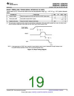
Register Initialization
After power-up, the internal registers MUST be initialized to their default values. This can be done in one of two
ways:
1. Either through hardware reset by applying a high-going pulse on RESET pin (of width greater than 10ns) as
shown in Figure 8
OR
2. By applying software reset. Using the serial interface, set the <RESET> bit (D7 in register 0x00) to HIGH.
This initializes internal registers to their default values and then self-resets the <RESET> bit to low. In this
case the RESET pin is kept low.
Register Address
Register Data
SDATA
A7
A6
A5
A4
A3
A2
A1
A0
D7
D6
D5
D4
D3
D2
t(DH)
D1
D0
t(SCLK)
t(DSU)
SCLK
t(SLOADH)
t(SLOADS)
SEN
RESET
T0109-01
Figure 8. Serial Interface Timing
16
Submit Documentation Feedback
Copyright © 2009, Texas Instruments Incorporated
Product Folder Link(s): ADS62P49 / ADS62P29 ADS62P48 / ADS62P28

 TI [ TEXAS INSTRUMENTS ]