ADS131M04-Q1
ZHCSOL7A –MARCH 2022 –REVISED AUGUST 2022
www.ti.com.cn
Every time the device swaps the input polarity, the digital filter is reset. The ADC then always takes three internal
conversions to produce one settled global-chop conversion result.
The ADS131M04-Q1 provides a programmable delay (tGC_DLY) between the end of the previous conversion
period and the beginning of the subsequent conversion period after the input polarity is swapped. This delay
allows external input circuitry to settle because the chopping switches interface directly with the analog inputs.
The GC_DLY[3:0] bits in the GLOBAL_CHOP_CFG register configure the delay after chopping the inputs. The
global-chop delay is selected in terms of modulator clock periods from 2 to 65,536 x tMOD
.
The effective conversion period in global-chop mode follows 方程式 8. A DRDY falling edge is generated each
time a new global-chop conversion becomes available to the host.
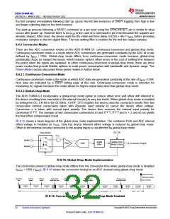
The conversion process of all ADC channels in global-chop mode is restarted in the following two conditions so
that all channels start sampling at the same time:
• Falling edge of the SYNC/RESET pin
• Change of OSR setting
The conversion period of the first conversion after the ADC channels are reset is considerably longer than the
conversion period of all subsequent conversions mentioned in 方程式 8, because the device must first perform
two fully settled internal conversions with the input polarity swapped. The conversion period for the first
conversion in global-chop mode follows 方程式9.
tGC_CONVERSION = tGC_DLY + 3 × OSR x tMOD
(8)
(9)
tGC_FIRST_CONVERSION = tGC_DLY + 3 × OSR x tMOD + tGC_DLY + 3 × OSR x tMOD + 44 x tMOD
Using global-chop mode reduces the ADC noise shown in 表 7-1 at a given OSR by a factor of √2 because two
consecutive internal conversions are averaged to yield one global-chop conversion result. The DC test signal
cannot be measured in global-chop mode.
Phase calibration is automatically disabled in global-chop mode.
8.4.4 Power Modes
In both continuous-conversion and global-chop mode, there are three selectable power modes that allow scaling
of power with bandwidth and performance: high-resolution (HR) mode, low-power (LP) mode, and very-low-
power (VLP) mode. The mode is selected by the PWR[1:0] bits in the CLOCK register. See the Recommended
Operating Conditions table for restrictions on the CLKIN frequency for each power mode.
8.4.5 Standby Mode
Standby mode is a low-power state in which all channels are disabled, and the reference and other non-
essential circuitry are powered down. This mode differs from completely powering down the device because the
device retains the register settings. Enter standby mode by sending the STANDBY command (0022h). Stop
toggling CLKIN when the device is in standby mode to minimize device power consumption. Exit standby mode
by sending the WAKEUP command (0033h). After exiting standby mode, the modulators begin sampling the
input signal after a modulator settling time of 8 × tMOD when CLKIN begins toggling.
8.4.6 Current-Detect Mode
Current-detect mode is a special mode that is helpful for applications requiring tamper detection when the
equipment is in a low-power state. In this mode, the ADS131M04-Q1 collects a configurable number of samples
at a nominal data rate of 2.7 kSPS and compares the absolute value of the results to a programmable threshold.
If a configurable number of results exceed the threshold, the host is notified via a DRDY falling edge and the
device returns to standby mode. Enter current-detect mode by providing a negative pulse on SYNC/RESET with
a pulse duration less than tw(RSL) when in standby mode. Current-detect mode can only be entered from standby
mode.
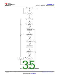
The device uses a limited power operating mode to generate conversions in current-detect mode. The
conversion results are only used for comparison by the internal digital threshold comparator and are not
accessible by the host. The device uses an internal oscillator that enables the device to capture the data without
Copyright © 2022 Texas Instruments Incorporated
Submit Document Feedback
33
Product Folder Links: ADS131M04-Q1

 TI [ TEXAS INSTRUMENTS ]