ADS131M04-Q1
ZHCSOL7A –MARCH 2022 –REVISED AUGUST 2022
www.ti.com.cn
words are clocked out. Terminating the frame early causes the RESET command to be ignored. Six words are
required to complete a frame on the ADS131M04-Q1.
A reset occurs immediately after the command is latched. The host must wait for tREGACQ before communicating
with the device to ensure the registers have assumed their default settings. Conversion data are generated
immediately after the registers are reset to their default values, as described in the Fast Start-Up Behavior
section.
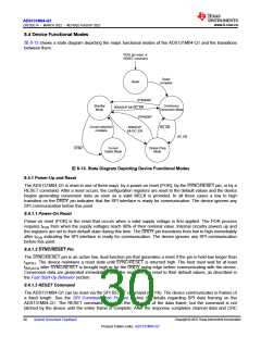
8.4.2 Fast Start-Up Behavior
The ADS131M04-Q1 begins generating conversion data shortly after startup as soon as a valid CLKIN signal is
provided to the ΔΣ modulators. The fast start-up feature is useful for applications such as circuit breakers
powered from the mains that require a fast determination of the input voltage soon after power is applied to the
device. Fast start up is accomplished via two mechanisms. First, the device internal power-supply circuitry is
designed specifically to enable fast start up. Second, the digital decimation filter dynamically switches from a
fast-settling filter to a sinc3 filter when the sinc3 filter has had time to settle.
After the supplies are ramped to 90% of their final values, the device requires tPOR for the internal circuitry to
settle. The end of tPOR is indicated by a transition of DRDY from low to high. The transition of DRDY from low to
high also indicates the SPI interface is ready to accept commands.
The ΔΣ modulators of the ADS131M04-Q1 require CLKIN to toggle after tPOR to begin working. The
modulators begin sampling the input signal after an initial wait time delay of (256 + 44) × tMOD when CLKIN
begins toggling. Therefore, provide a valid clock signal on CLKIN as soon as possible after the supply ramp to
achieve the fastest possible startup time.
The data generated by the ΔΣ modulators are fed to the digital filter blocks. The data are provided to both the
fast-settling filter and the sinc3 filter paths. The fast-settling filter requires only one data rate period to provide
settled data. Meanwhile, the sinc3 filter requires three data rate periods to settle. The fast-settling filter generates
the output data for the two interim ADC output samples indicated by DRDY transitioning from high to low while
the sinc3 filter is settling. The device disables the fast-settling filter and provides conversion data from the sinc3
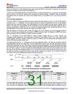
filter path for the third and following samples. 图 8-14 shows the behavior of the fast start-up feature when using
an external clock that is provided to the device right after the supplies have ramped. 表 8-8 shows the values for
the various start-up and settling times relevant to the device start up.
90%
tSETTLE3
tDATA
Supplies
tPOR
tSETTLE1
tDATA
DRDY
Fast-settling
filter data
Fast-settling
filter data
Sinc3
filter data
Sinc3
filter data
...
...
...
...
CLKIN
图8-14. Fast Startup Behavior and Settling Times
表8-8. Fast Startup Settling Times for Default OSR = 1024
VALUE (DETAILS)
(tMOD
VALUE
(tMOD
VALUE AT
fCLKIN = 8.192 MHz (ms)
PARAMETER
)
)
tDATA = 1/fDATA
tSETTLE1
1024
1024
1324
3372
0.250
0.323
0.823
256 + 44 + 1024
256 + 44 + 3 x 1024
tSETTLE3
The fast-settling filter provides conversion data that are significantly noisier than the data that comes from the
sinc3 filter path, but allows the device to provide settled conversion data during the longer settling time of the
more accurate sinc3 digital filter. If the level of precision provided by the fast-settling filter is insufficient even for
Copyright © 2022 Texas Instruments Incorporated
Submit Document Feedback
31
Product Folder Links: ADS131M04-Q1

 TI [ TEXAS INSTRUMENTS ]