ADS131M04-Q1
ZHCSOL7A –MARCH 2022 –REVISED AUGUST 2022
www.ti.com.cn
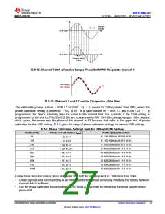
Sample
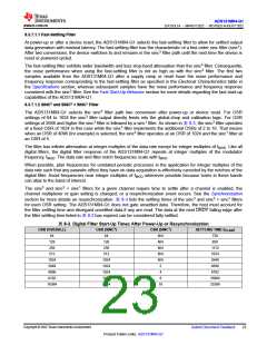
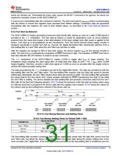
Period
CH0 Input
CH1 Input
Sample Period
Offset
图8-10. Channel 1 With a Positive Sample Phase Shift With Respect to Channel 0
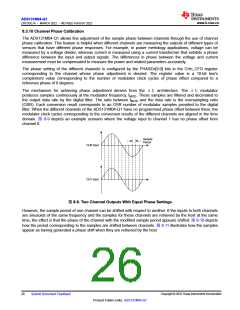
CH0 Output
CH1 Output
图8-11. Channels 1 and 0 From the Perspective of the Host
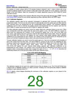
The valid setting range is from –OSR / 2 to (OSR / 2) – 1, except for OSRs greater than 1024, where the
phase calibration setting is limited to –512 to 511. If a value outside of –OSR / 2 and (OSR / 2) – 1 is
programmed, the device internally clips the value to the nearest limit. For example, if the OSR setting is
programmed to 128 and the PHASEn[9:0] bits are programmed to 0001100100b corresponding to 100 modulator
clock cycles, the device sets the phase of the channel to 63 because that value is the upper limit of phase
calibration for that OSR setting. 表8-5 gives the range of phase calibration settings for various OSR settings.
表8-5. Phase Calibration Setting Limits for Different OSR Settings
OSR SETTING
PHASE OFFSET RANGE (tMOD
)
PHASEn[9:0] BITS RANGE
64
11 1110 0000b to 00 0001 1111b
–32 to 31
128
256
11 1100 0000b to 00 0011 1111b
11 1000 0000b to 00 0111 1111b
11 0000 0000b to 00 1111 1111b
10 0000 0000b to 01 1111 1111b
10 0000 0000b to 01 1111 1111b
10 0000 0000b to 01 1111 1111b
10 0000 0000b to 01 1111 1111b
10 0000 0000b to 01 1111 1111b
–64 to 63
–128 to 127
512
–256 to 255
1024
2048
4096
8192
16384
–512 to 511
–512 to 511
–512 to 511
–512 to 511
–512 to 511
Follow these steps to create a phase shift larger than half the sample period for OSRs less than 2048:
• Create a phase shift corresponding to an integer number of sample periods by modifying the indices between
channel data in software
• Use the phase calibration function of the ADS131M04-Q1 to create the remaining fractional sample period
phase shift
Copyright © 2022 Texas Instruments Incorporated
Submit Document Feedback
27
Product Folder Links: ADS131M04-Q1

 TI [ TEXAS INSTRUMENTS ]