ADS131M04-Q1
ZHCSOL7A –MARCH 2022 –REVISED AUGUST 2022
www.ti.com.cn
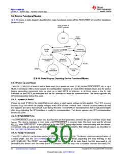
8.3.10 Channel Phase Calibration
The ADS131M04-Q1 allows fine adjustment of the sample phase between channels through the use of channel
phase calibration. This feature is helpful when different channels are measuring the outputs of different types of
sensors that have different phase responses. For example, in power metrology applications, voltage can be
measured by a voltage divider, whereas current is measured using a current transformer that exhibits a phase
difference between the input and output signals. The differences in phase between the voltage and current
measurement must be compensated to measure the power and related parameters accurately.
The phase setting of the different channels is configured by the PHASEn[9:0] bits in the CHn_CFG register
corresponding to the channel whose phase adjustment is desired. The register value is a 10-bit two's
complement value corresponding to the number of modulator clock cycles of phase offset compared to a
reference phase of 0 degrees.
The mechanism for achieving phase adjustment derives from the ΔΣ architecture. The ΔΣ modulator
produces samples continuously at the modulator frequency, fMOD. These samples are filtered and decimated to
the output data rate by the digital filter. The ratio between fMOD and the data rate is the oversampling ratio
(OSR). Each conversion result corresponds to an OSR number of modulator samples provided to the digital
filter. When the different channels of the ADS131M04-Q1 have no programmed phase offset between them, the
modulator clock cycles corresponding to the conversion results of the different channels are aligned in the time
domain. 图 8-9 depicts an example scenario where the voltage input to channel 1 has no phase offset from
channel 0.
Sample
Period
CH0 Input
CH1 Input
图8-9. Two Channel Outputs With Equal Phase Settings
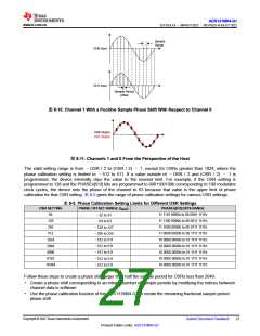
However, the sample period of one channel can be shifted with respect to another. If the inputs to both channels
are sinusoids of the same frequency and the samples for these channels are retrieved by the host at the same
time, the effect is that the phase of the channel with the modified sample period appears shifted. 图 8-10 depicts
how the period corresponding to the samples are shifted between channels. 图 8-11 illustrates how the samples
appear as having generated a phase shift when they are retrieved by the host.
Copyright © 2022 Texas Instruments Incorporated
26
Submit Document Feedback
Product Folder Links: ADS131M04-Q1

 TI [ TEXAS INSTRUMENTS ]