ADS131B04-Q1
ZHCSMK3B –NOVEMBER 2020 –REVISED NOVEMBER 2021
www.ti.com.cn
8.5.3 Commands
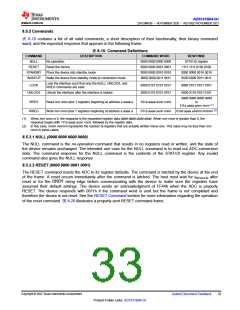
表 8-10 contains a list of all valid commands, a short description of their functionality, their binary command
word, and the expected response that appears in the following frame.
表8-10. Command Definitions
COMMAND
NULL
DESCRIPTION
COMMAND WORD
0000 0000 0000 0000
0000 0000 0001 0001
0000 0000 0010 0010
0000 0000 0011 0011
RESPONSE
No operation
STATUS register
RESET
Reset the device
1111 1111 0100 0100
0000 0000 0010 0010
0000 0000 0011 0011
STANDBY
WAKEUP
Place the device into standby mode
Wake the device from standby mode to conversion mode
Lock the interface such that only the NULL, UNLOCK, and
RREG commands are valid
LOCK
0000 0101 0101 0101
0000 0110 0101 0101
0000 0101 0101 0101
0000 0110 0101 0101
UNLOCK
Unlock the interface after the interface is locked
dddd dddd dddd dddd
or
RREG
WREG
Read nnn nnnn plus 1 registers beginning at address a aaaa a
Write nnn nnnn plus 1 registers beginning at address a aaaa a
101a aaaa annn nnnn
011a aaaa annn nnnn
111a aaaa annn nnnn (1)
010a aaaa ammm mmmm (2)
(1) When nnn nnnn is 0, the response is the requested register data dddd dddd dddd dddd. When nnn nnnn is greater than 0, the
response begins with 111a aaaa annn nnnn, followed by the register data.
(2) In this case, mmm mmmm represents the number of registers that are actually written minus one. This value may be less than nnn
nnnn in some cases.
8.5.3.1 NULL (0000 0000 0000 0000)
The NULL command is the no-operation command that results in no registers read or written, and the state of
the device remains unchanged. The intended use case for the NULL command is to read out ADC conversion
data. The command response for the NULL command is the contents of the STATUS register. Any invalid
command also gives the NULL response.
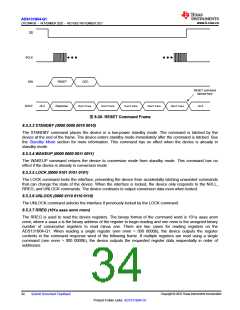
8.5.3.2 RESET (0000 0000 0001 0001)
The RESET command resets the ADC to its register defaults. The command is latched by the device at the end
of the frame. A reset occurs immediately after the command is latched. The host must wait for tREGACQ after
reset or for the DRDY rising edge before communicating with the device to make sure the registers have
assumed their default settings. The device sends an acknowledgment of FF44h when the ADC is properly
RESET. The device responds with 0011h if the command word is sent but the frame is not completed and
therefore the device is not reset. See the RESET Command section for more information regarding the operation
of the reset command. 图8-20 illustrates a properly sent RESET command frame.
Copyright © 2022 Texas Instruments Incorporated
Submit Document Feedback
33
Product Folder Links: ADS131B04-Q1

 TI [ TEXAS INSTRUMENTS ]