ADS131B04-Q1
ZHCSMK3B –NOVEMBER 2020 –REVISED NOVEMBER 2021
www.ti.com.cn
8.4.2 Fast Start-Up Behavior
The ADS131B04-Q1 begins generating conversion data shortly after start-up as soon as a valid MCLK signal is
provided to the ΔΣ modulators. Fast start-up is accomplished via two mechanisms. First, the device internal
power-supply circuitry is designed specifically to enable fast start-up. Second, the digital decimation filter
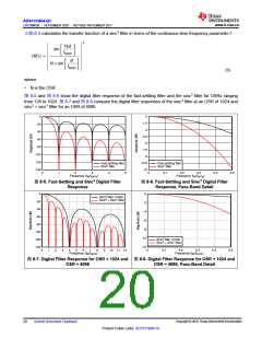
dynamically switches from a fast-settling filter to a sinc3 filter when the sinc3 filter has settled.
After the supplies are ramped to 90% of their final values, the device requires tPOR for the internal circuitry to
settle. The end of tPOR is indicated by a transition of DRDY from low to high. The transition of DRDY from low to
high also indicates the SPI interface is ready to accept commands.
The ΔΣ modulators of the ADS131B04-Q1 require CLKIN to toggle after tPOR to begin working, or alternatively,
activate the internal oscillator by setting the CLK_SEL bit in the CLOCK register. The modulators begin sampling
the input signal after an initial wait time delay of (256 + 44) × tMOD when MCLK begins toggling. Therefore, when
using an external clock, provide a valid clock signal on CLKIN as soon as possible after the supply ramp to
achieve the fastest possible start-up time.
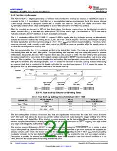
The data generated by the ΔΣ modulators are fed to the digital filter blocks. The data are provided to both the
fast-settling filter and the sinc3 filter paths. The fast-settling filter requires only one data rate period to provide
settled data. Meanwhile, the sinc3 filter requires three data rate periods to settle. The fast-settling filter generates
the output data for the two interim ADC output samples indicated by DRDY transitioning from high to low while
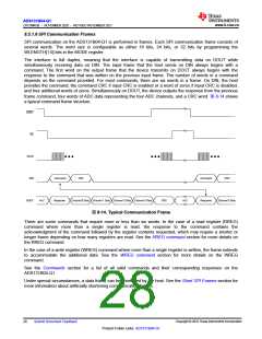
the sinc3 filter is settling. The device disables the fast-settling filter and provides conversion data from the sinc3
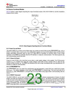
filter path for the third and following samples. 图 8-11 shows the behavior of the fast-start-up feature when using
an external clock that is provided to the device right after the supplies have ramped. 表 8-7 shows the values for
the various start-up and settling times relevant to the device start-up.
90%
tSETTLE3
tDATA
Supplies
tPOR
tSETTLE1
tDATA
DRDY
Fast-settling
filter data
Fast-settling
filter data
Sinc3
filter data
Sinc3
filter data
...
...
...
...
CLKIN
图8-11. Fast Start-Up Behavior and Settling Times
表8-7. Fast Start-Up Settling Times for Default OSR = 1024
VALUE (DETAILS)
(tMOD
VALUE
(tMOD
VALUE AT
fMCLK = 8.192 MHz (ms)
PARAMETER
)
)
tDATA = 1/fDATA
tSETTLE1
1024
1024
1324
3372
0.250
0.323
0.823
256 + 44 + 1024
256 + 44 + 3 × 1024
tSETTLE3
The fast-settling filter provides conversion data that are significantly noisier than the data that comes from the
sinc3 filter path, but allows the device to provide settled conversion data during the longer settling time of the
more accurate sinc3 digital filter. If the level of precision provided by the fast-settling filter is insufficient even for
the first samples immediately following start-up, ignore the first two instances of DRDY toggling from high to low
and begin collecting data on the third instance.
The start-up process following a RESET command or a pin reset using the SYNC/RESET pin is similar to what
occurs after power up. However there is no tPOR in the case of a command or pin reset because the supplies are
already ramped. After reset, the device waits for the initial wait time delay of (256 + 44) × tMOD before providing
modulator samples to the two digital filters. The fast-settling filter is enabled for the first two output samples.
Remember to enable the internal oscillator every time again after a reset in case the internal oscillator is to be
used, because the device defaults to using an external clock.
Copyright © 2022 Texas Instruments Incorporated
24
Submit Document Feedback
Product Folder Links: ADS131B04-Q1

 TI [ TEXAS INSTRUMENTS ]