ADS1291
ADS1292
ADS1292R
www.ti.com
SBAS502A –DECEMBER 2011–REVISED MARCH 2012
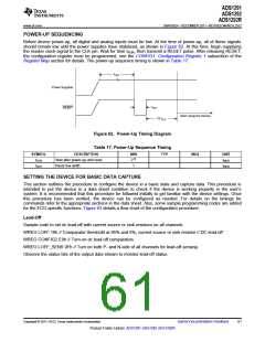
POWER-UP SEQUENCING
Before device power-up, all digital and analog inputs must be low. At the time of power-up, all of these signals
should remain low until the power supplies have stabilized, as shown in Figure 62. At this time, begin supplying
the master clock signal to the CLK pin. Wait for time tPOR, then transmit a RESET pulse. After releasing RESET,
the configuration register must be programmed, see the CONFIG1: Configuration Register 1 subsection of the
Register Map section for details. The power-up sequence timing is shown in Table 17.
tPOR
Power Supplies
tRST
RESET
Start Using the Device
18 tCLK
Figure 62. Power-Up Timing Diagram
Table 17. Power-Up Sequence Timing
SYMBOL
tPOR
DESCRIPTION
Wait after power-up until reset
Reset low width
MIN
212
1
TYP
MAX
UNIT
tMOD
tMOD
tRST
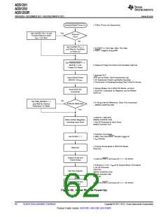
SETTING THE DEVICE FOR BASIC DATA CAPTURE
This section outlines the procedure to configure the device in a basic state and capture data. This procedure is
intended to put the device in a data sheet condition to check if the device is working properly in the user's
system. It is recommended that this procedure be followed initially to get familiar with the device settings. Once
this procedure has been verified, the device can be configured as needed. For details on the timings for
commands refer to the appropriate sections in the data sheet. Also, some sample programming codes are added
for the ECG-specific functions. Figure 63 details a flow chart of the configuration procedure.
Lead-Off
Sample code to set dc lead-off with current source or sink resistors on all channels
WREG LOFF 10h // Comparator threshold at 95% and 5%, current source or sink resistor // DC lead-off
WREG CONFIG2 E0h // Turn-on dc lead-off comparators
WREG LOFF_SENS 0Fh // Turn on both P- and N-side of all channels for lead-off sensing
Observe the status bits of the output data stream to monitor lead-off status.
Copyright © 2011–2012, Texas Instruments Incorporated
Submit Documentation Feedback
61
Product Folder Link(s): ADS1291 ADS1292 ADS1292R

 TI [ TEXAS INSTRUMENTS ]