ADS1291
ADS1292
ADS1292R
www.ti.com
SBAS502A –DECEMBER 2011–REVISED MARCH 2012
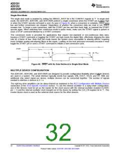
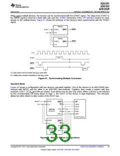
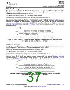
When using multiple devices, the devices can be synchronized with the START signal. The delay from START to
the DRDY signal is fixed for a fixed data rate (see the START subsection of the SPI Interface section for more
details on the settling times). Figure 41 shows the behavior of two devices when synchronized with the START
signal.
Device1
START
CLK
START1
CLK
DRDY1
DRDY
Device2
START2
CLK
DRDY2
DRDY
CLK
Note 1
START
DRDY1
DRDY2
Note 2
(1) Start pulse must be at least one tMOD cycle wide.
(2) Settling time number uncertainty is one tMOD cycle.
Figure 41. Synchronizing Multiple Converters
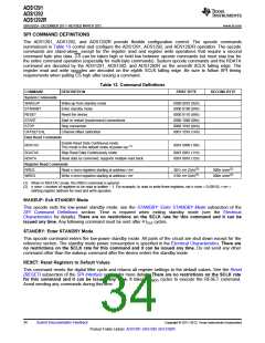
Standard Mode
Figure 42 shows a configuration with two devices cascaded together. One of the devices is an ADS1292R (two-
channel with RESP) and the other is an ADS1292 (two-channel). Together, they create a system with four
channels. DOUT, SCLK, and DIN are shared. Each device has its own chip select. When a device is not selected
by the corresponding CS being driven to logic 1, the DOUT of this device is high-impedance. This structure
allows the other device to take control of the DOUT bus.
START(1)
START
DRDY
CS
INT
CLK
CLK
GPO0
GPO1
SCLK
MOSI
MISO
SCLK
DIN
ADS1292
(Device 0)
DOUT
Host Processor
START
CLK
DRDY
CS
SCLK
DIN
ADS1292R
(Device 1)
DOUT
Figure 42. Multiple Device Configurations
Copyright © 2011–2012, Texas Instruments Incorporated
Submit Documentation Feedback
33
Product Folder Link(s): ADS1291 ADS1292 ADS1292R

 TI [ TEXAS INSTRUMENTS ]