ADS1291
ADS1292
ADS1292R
www.ti.com
SBAS502A –DECEMBER 2011–REVISED MARCH 2012
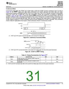
DATA FORMAT
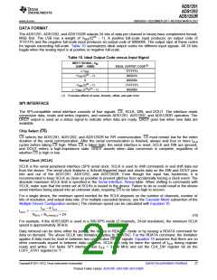
The ADS1291, ADS1292, and ADS1292R outputs 24 bits of data per channel in binary twos complement format,
MSB first. The LSB has a weight of VREF/(223 – 1). A positive full-scale input produces an output code of
7FFFFFh and the negative full-scale input produces an output code of 800000h. The output clips at these codes
for signals exceeding full-scale. Table 10 summarizes ideal output codes for different input signals. All 24 bits
toggle when the analog input is at positive or negative full-scale.
Table 10. Ideal Output Code versus Input Signal
INPUT SIGNAL, VIN
(AINP – AINN)
IDEAL OUTPUT CODE(1)
7FFFFFh
≥ VREF
+VREF/(223 – 1)
0
000001h
000000h
–VREF/(223 – 1)
≤ –VREF (223/223 – 1)
FFFFFFh
800000h
(1) Excludes effects of noise, linearity, offset, and gain error.
SPI INTERFACE
The SPI-compatible serial interface consists of four signals: CS, SCLK, DIN, and DOUT. The interface reads
conversion data, reads and writes registers, and controls ADS1291, ADS1292, and ADS1292R operation. The
DRDY output is used as a status signal to indicate when data are ready. DRDY goes low when new data are
available.
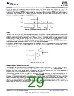
Chip Select (CS)
CS selects the ADS1291, ADS1292, and ADS1292R for SPI communication. CS must remain low for the entire
duration of the serial communication. After the serial communication is finished, always wait four or more tCLK
cycles before taking CS high. When CS is taken high, the serial interface is reset, SCLK and DIN are ignored,
and DOUT enters a high-impedance state. DRDY asserts when data conversion is complete, regardless of
whether CS is high or low.
Serial Clock (SCLK)
SCLK is the serial peripheral interface (SPI) serial clock. SCLK is used to shift commands in and shift data out
from the device. The serial clock features a Schmitt-triggered input and clocks data on the DIN and DOUT pins
into and out of the ADS1291, ADS1292, and ADS1292R. Even though the input has hysteresis, it is
recommended to keep SCLK as clean as possible to prevent glitches from accidentally forcing a clock event. The
absolute maximum SCLK limit is specified in the Serial Interface Timing table. When shifting in commands with
SCLK, make sure that the entire set of SCLKs is issued to the device. Failure to do so could result in the device
serial interface being placed into an unknown state, requiring CS to be taken high to recover.
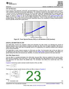
For a single device, the minimum speed needed for the SCLK depends on the number of channels, number of
bits of resolution, and output data rate. (For multiple cascaded devices, see the Cascade Mode subsection of the
Multiple Device Configuration section.) The minimum speed can be calculated with Equation 10.
tDR - 4 tCLK
tSCLK
<
N
BITS ´ NCHANNELS + 24
(10)
For example, if the ADS1292R is used in a 500-SPS mode (2 channels, 24-bit resolution), the minimum SCLK
speed is approximately 36 kHz.
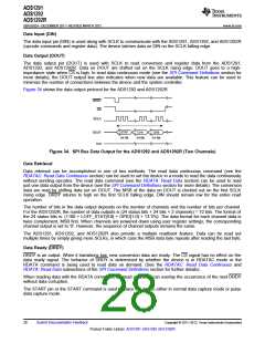
Data retrieval can be done either by putting the device in RDATAC mode or by issuing a RDATA command for
data on demand. The above SCLK rate limitation applies to RDATAC. For the RDATA command, the limitation
applies if data must be read in between two consecutive DRDY signals. Equation 10 assumes that there are no
other commands issued in between data captures. SCLK can only be twice the speed of fCLK during register
reads and writes. For faster SPI interface, use fCLK = 2.048 MHz and set the CLK_DIV register bit (in the
LOFF_STAT register) to '1'.
Copyright © 2011–2012, Texas Instruments Incorporated
Submit Documentation Feedback
27
Product Folder Link(s): ADS1291 ADS1292 ADS1292R

 TI [ TEXAS INSTRUMENTS ]