ADS1291
ADS1292
ADS1292R
SBAS502A –DECEMBER 2011–REVISED MARCH 2012
www.ti.com
Data Input (DIN)
The data input pin (DIN) is used along with SCLK to communicate with the ADS1291, ADS1292, and ADS1292R
(opcode commands and register data). The device latches data on DIN on the SCLK falling edge.
Data Output (DOUT)
The data output pin (DOUT) is used with SCLK to read conversion and register data from the ADS1291,
ADS1292, and ADS1292R. Data on DOUT are shifted out on the SCLK rising edge. DOUT goes to a high-
impedance state when CS is high. In read data continuous mode (see the SPI Command Definitions section for
more details), the DOUT output line also indicates when new data are available. This feature can be used to
minimize the number of connections between the device and the system controller.
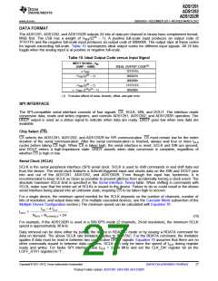
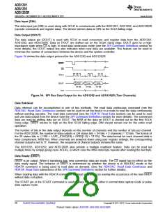
Figure 34 shows the data output protocol for the ADS1292 and ADS1292R.
DRDY
CS
SCLK
DOUT
DIN
STAT
CH1
CH2
24-Bit
24-Bit
24-Bit
Figure 34. SPI Bus Data Output for the ADS1292 and ADS1292R (Two Channels)
Data Retrieval
Data retrieval can be accomplished in one of two methods. The read data continuous command (see the
RDATAC: Read Data Continuous section) can be used to set the device in a mode to read the data continuously
without sending opcodes. The read data command (see the RDATA: Read Data section) can be used to read
just one data output from the device (see the SPI Command Definitions section for more details). The conversion
data are read by shifting data out on DOUT. The MSB of the data on DOUT is clocked out on the first SCLK
rising edge. DRDY returns to high on the first SCLK falling edge. DIN should remain low for the entire read
operation.
The number of bits in the data output depends on the number of channels and the number of bits per channel.
For the ADS1292R, the number of data outputs is (24 status bits + 24 bits × 2 channels) = 72 bits. The format of
the 24 status bits is: (1100 + LOFF_STAT[4:0] + GPIO[1:0] + 13 '0's). The data format for each channel data is
twos complement, MSB first. When channels are powered down using user register settings, the corresponding
channel output is set to '0'. However, the sequence of channel outputs remains the same.
The ADS1291, ADS1292, and ADS1292R also provide a multiple readback feature. Data can be read out
multiple times by simply giving more SCLKs, in which case the MSB data byte repeats after reading the last byte.
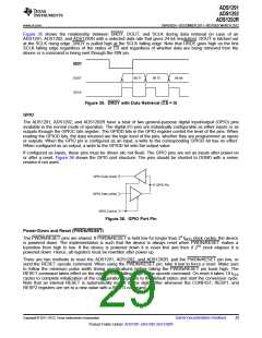
Data Ready (DRDY)
DRDY is an output. When it transitions low, new conversion data are ready. The CS signal has no effect on the
data ready signal. The behavior of DRDY is determined by whether the device is in RDATAC mode or the
RDATA command is being used to read data on demand. (See the RDATAC: Read Data Continuous and
RDATA: Read Data subsections of the SPI Command Definitions section for further details).
When reading data with the RDATA command, the read operation can overlap the occurrence of the next DRDY
without data corruption.
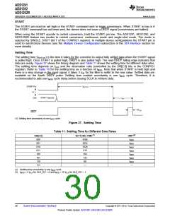
The START pin or the START command is used to place the device either in normal data capture mode or pulse
data capture mode.
28
Submit Documentation Feedback
Copyright © 2011–2012, Texas Instruments Incorporated
Product Folder Link(s): ADS1291 ADS1292 ADS1292R

 TI [ TEXAS INSTRUMENTS ]