ADS1299
www.ti.com
SBAS499A –JULY 2012–REVISED AUGUST 2012
SDATAC: Stop Read Data Continuous
This opcode cancels the Read Data Continuous mode. There are no SCLK rate restrictions for this command,
but the next command must wait for 4 tCLK cycles.
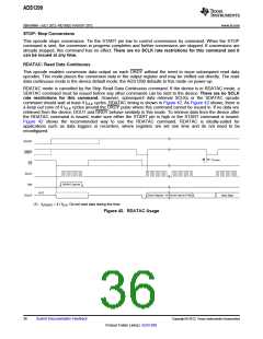
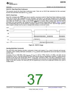
RDATA: Read Data
Issue this command after DRDY goes low to read the conversion result (in Stop Read Data Continuous mode).
There are no SCLK rate restrictions for this command, and there is no wait time needed for the subsequent
commands or data retrieval SCLKs. To retrieve data from the device after the RDATA command is issued, make
sure either the START pin is high or the START command is issued. When reading data with the RDATA
command, the read operation can overlap the next DRDY occurrence without data corruption. Figure 43 shows
the recommended way to use the RDATA command. RDATA is best suited for ECG- and EEG-type systems,
where register settings must be read or changed often between conversion cycles.
START
DRDY
CS
SCLK
RDATA Opcode
RDATA Opcode
DIN
Hi-Z
Status Register+ 8-Channel Data (216 Bits)
DOUT
Figure 43. RDATA Usage
Sending Multi-Byte Commands
The ADS1299 serial interface decodes commands in bytes and requires 4 tCLK cycles to decode and execute.
Therefore, when sending multi-byte commands, a 4 tCLK period must separate the end of one byte (or opcode)
and the next.
Assuming CLK is 2.048 MHz, then tSDECODE (4 tCLK) is 1.96 µs. When SCLK is 16 MHz, one byte can be
transferred in 500 ns. This byte transfer time does not meet the tSDECODE specification; therefore, a delay must be
inserted so the end of the second byte arrives 1.46 µs later. If SCLK is 4 MHz, one byte is transferred in 2 µs.
Because this transfer time exceeds the tSDECODE specification, the processor can send subsequent bytes without
delay. In this later scenario, the serial port can be programmed to move from single-byte transfers per cycle to
multiple bytes.
Copyright © 2012, Texas Instruments Incorporated
Submit Documentation Feedback
37
Product Folder Link(s): ADS1299

 TI [ TEXAS INSTRUMENTS ]