ADS1299
SBAS499A –JULY 2012–REVISED AUGUST 2012
www.ti.com
When all devices in the chain operate in the same register setting, DIN can be shared as well. This configuration
reduces the SPI communication signals to four, regardless of the number of devices. However, because the
individual devices cannot be programmed, the BIAS driver cannot be shared among the multiple devices.
Furthermore, an external clock must be used.
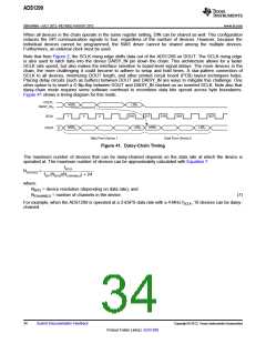
Note that from Figure 2, the SCLK rising edge shifts data out of the ADS1299 on DOUT. The SCLK rising edge
is also used to latch data into the device DAISY_IN pin down the chain. This architecture allows for a faster
SCLK rate speed, but also makes the interface sensitive to board-level signal delays. The more devices in the
chain, the more challenging it could become to adhere to setup and hold times. A star-pattern connection of
SCLK to all devices, minimizing DOUT length, and other printed circuit board (PCB) layout techniques helps.
Placing delay circuits (such as buffers) between DOUT and DAISY_IN are ways to mitigate this challenge. One
other option is to insert a D flip-flop between DOUT and DAISY_IN clocked on an inverted SCLK. Note also that
daisy-chain mode requires some software overhead to recombine data bits spread across byte boundaries.
Figure 41 shows a timing diagram for this mode.
DOUT1
MSB1
LSB1
DAISY_IN0
SCLK
1
2
3
216
217
218
219
337
MSB0
LSB0
MSB1
LSB1
DOUT
0
Data From Device 1
Data From Device 2
Figure 41. Daisy-Chain Timing
The maximum number of devices that can be daisy-chained depends on the data rate at which the device is
operated at. The maximum number of devices can be approximately calculated with Equation 7.
fSCLK
NDEVICES
=
fDR (NBITS)(NCHANNELS) + 24
where:
NBITS = device resolution (depending on data rate), and
NCHANNELS = number of channels in the device.
(7)
For example, when the ADS1299 is operated at a 2-kSPS data rate with a 4-MHz fSCLK, 10 devices can be daisy-
chained.
34
Submit Documentation Feedback
Copyright © 2012, Texas Instruments Incorporated
Product Folder Link(s): ADS1299

 TI [ TEXAS INSTRUMENTS ]