ADS1299
www.ti.com
SBAS499A –JULY 2012–REVISED AUGUST 2012
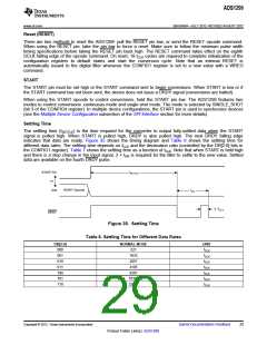
Standard Mode
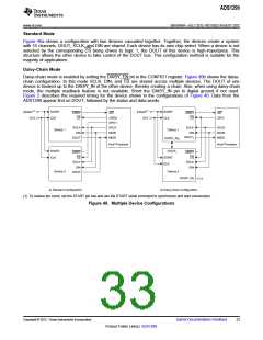
Figure 40a shows a configuration with two devices cascaded together. Together, the devices create a system
with 16 channels. DOUT, SCLK, and DIN are shared. Each device has its own chip select. When a device is not
selected by the corresponding CS being driven to logic 1, the DOUT of this device is high-impedance. This
structure allows the other device to take control of the DOUT bus. This configuration method is suitable for the
majority of applications.
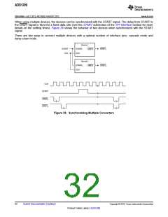
Daisy-Chain Mode
Daisy-chain mode is enabled by setting the DAISY_EN bit in the CONFIG1 register. Figure 40b shows the daisy-
chain configuration. In this mode SCLK, DIN, and CS are shared across multiple devices. The DOUT of one
device is hooked up to the DAISY_IN of the other device, thereby creating a chain. Also, when using daisy-chain
mode, the multiple readback feature is not available. Short the DAISY_IN pin to digital ground if not used.
Figure 2 describes the required timing for the device shown in the configurations of Figure 40. Data from the
ADS1299 appear first on DOUT, followed by the status and data words.
START(1)
CLK
START(1)
CLK
START
CLK
START
CLK
DRDY
CS
INT
DRDY
CS
INT
GPO0
GPO1
SCLK
MOSI
MISO
GPO
SCLK
DIN
SCLK
DIN
SCLK
MOSI
MISO
Device 1
Device 1
DOUT0
DOUT
DAISY_IN0
Host Processor
Host Processor
START
CLK
DOUT1
START
CLK
DRDY
CS
DRDY
CS
SCLK
DIN
SCLK
DIN
Device 2
Device 2
DOUT
DAISY_IN1
0
a) Standard Configuration
b) Daisy-Chain Configuration
(1) To reduce pin count, set the START pin low and use the START serial command to synchronize and start conversions.
Figure 40. Multiple Device Configurations
Copyright © 2012, Texas Instruments Incorporated
Submit Documentation Feedback
33
Product Folder Link(s): ADS1299

 TI [ TEXAS INSTRUMENTS ]