ADS1299
SBAS499A –JULY 2012–REVISED AUGUST 2012
www.ti.com
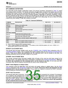
STOP: Stop Conversions
This opcode stops conversions. Tie the START pin low to control conversions by command. When the STOP
command is sent, the conversion in progress completes and further conversions are stopped. If conversions are
already stopped, this command has no effect. There are no SCLK rate restrictions for this command and it
can be issued at any time.
RDATAC: Read Data Continuous
This opcode enables conversion data output on each DRDY without the need to issue subsequent read data
opcodes. This mode places the conversion data in the output register and may be shifted out directly. The read
data continuous mode is the device default mode; the ADS1299 defaults to this mode on power-up.
RDATAC mode is cancelled by the Stop Read Data Continuous command. If the device is in RDATAC mode, a
SDATAC command must be issued before any other commands can be sent to the device. There are no SCLK
rate restrictions for this command. However, subsequent data retrieval SCLKs or the SDATAC opcode
command should wait at least 4 tCLK cycles. RDATAC timing is shown in Figure 42. As Figure 42 shows, there is
a keep out zone of 4 tCLK cycles around the DRDY pulse where this command cannot be issued in. If no data are
retrieved from the device, DOUT and DRDY behave similarly in this mode. To retrieve data from the device after
the RDATAC command is issued, make sure either the START pin is high or the START command is issued.
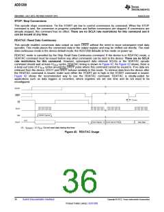
Figure 42 shows the recommended way to use the RDATAC command. RDATAC is ideally-suited for
applications such as data loggers or recorders, where registers are set one time and do not need to be
reconfigured.
START
DRDY
tUPDATE
CS
SCLK
RDATAC Opcode
DIN
Hi-Z
Status Register + 8-Channel Data (216 Bits)
DOUT
Next Data
(1) tUPDATE = 4 / fCLK. Do not read data during this time.
Figure 42. RDATAC Usage
36
Submit Documentation Feedback
Copyright © 2012, Texas Instruments Incorporated
Product Folder Link(s): ADS1299

 TI [ TEXAS INSTRUMENTS ]