ADS1299
www.ti.com
SBAS499A –JULY 2012–REVISED AUGUST 2012
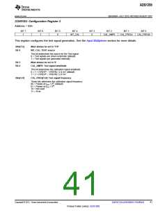
CONFIG2: Configuration Register 2
Address = 02h
BIT 7
1
BIT 6
1
BIT 5
0
BIT 4
BIT 3
0
BIT 2
BIT 1
BIT 0
INT_CAL
CAL_AMP0
CAL_FREQ1
CAL_FREQ0
This register configures the test signal generation. See the Input Multiplexer section for more details.
Bits[7:5]
Bit 4
Must always be set to '110'
INT_CAL: TEST source
This bit determines the source for the Test signal.
0 = Test signals are driven externally (default)
1 = Test signals are generated internally
Bit 3
Bit 2
Must always be set to '0'
CAL_AMP0: Test signal amplitude
This bit determines the calibration signal amplitude.
0 = 1 × (VREFP – VREFN) / 2.4 mV (default)
1 = 2 × (VREFP – VREFN) / 2.4 mV
Bits[1:0]
CAL_FREQ[1:0]: Test signal frequency
These bits determine the calibration signal frequency.
00 = Pulsed at fCLK / 221 (default)
01 = Pulsed at fCLK / 220
10 = Not used
11 = At dc
Copyright © 2012, Texas Instruments Incorporated
Submit Documentation Feedback
41
Product Folder Link(s): ADS1299

 TI [ TEXAS INSTRUMENTS ]