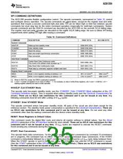
ADS1299
www.ti.com
SBAS499A –JULY 2012–REVISED AUGUST 2012
Single-Shot Mode
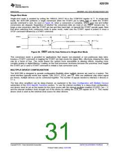
Single-shot mode is enabled by setting the SINGLE_SHOT bit in the CONFIG4 register to '1'. In single-shot
mode, the ADS1299 performs a single conversion when the START pin is taken high or when the START
opcode command is sent. As seen in Figure 38, when a conversion is complete, DRDY goes low and further
conversions are stopped. Regardless of whether the conversion data are read or not, DRDY remains low. To
begin a new conversion, take the START pin low and then back high, or transmit the START opcode again. Note
that when switching from continuous mode to pulse mode, make sure the START signal is pulsed or issue a
STOP command followed by a START command.
START
tSETTLE
4 / fCLK
4 / fCLK
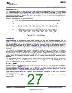
Data Updating
DRDY
Figure 38. DRDY with No Data Retrieval in Single-Shot Mode
This conversion mode is provided for applications that require non-standard or non-continuous data rates.
Issuing a START command or toggling the START pin high resets the digital filter, effectively dropping the data
rate by a factor of four. This mode leaves the system more susceptible to aliasing effects, requiring more
complex analog or digital filtering. Loading on the host processor increases because the processor must toggle
the START pin or send a START command to initiate a new conversion cycle.
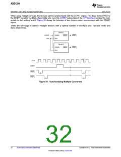
MULTIPLE DEVICE CONFIGURATION
The ADS1299 is designed to provide configuration flexibility when multiple devices are used in a system. The
serial interface typically needs four signals: DIN, DOUT, SCLK, and CS. With one additional chip select signal
per device, multiple devices can be connected together. The number of signals needed to interface n devices is
3 + n.
The bias drive amplifiers can be daisy-chained, as explained in the Bias Configuration with Multiple Devices
subsection of the EEG-Specific Functions section. To use the internal oscillator in a daisy-chain configuration,
one device must be set as the master for the clock source with the internal oscillator enabled (CLKSEL pin = 1)
and the internal oscillator clock brought out of the device by setting the CLK_EN register bit to '1'. This master
device clock is used as the external clock source for other devices.
Copyright © 2012, Texas Instruments Incorporated
Submit Documentation Feedback
31
Product Folder Link(s): ADS1299

 TI [ TEXAS INSTRUMENTS ]