ADS1299
SBAS499A –JULY 2012–REVISED AUGUST 2012
www.ti.com
Continuous Mode
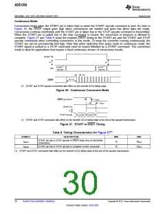
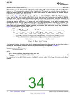
Conversions begin when the START pin is taken high or when the START opcode command is sent. As seen in
Figure 36, the DRDY output goes high when conversions are started and goes low when data are ready.
Conversions continue indefinitely until the START pin is taken low or the STOP opcode command is transmitted.
When the START pin is pulled low or the stop command is issued, the conversion in progress is allowed to
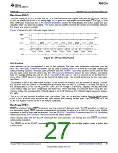
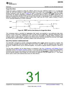
complete. Figure 37 and Table 9 show the required DRDY timing to the START pin and the START and STOP
opcode commands when controlling conversions in this mode. To keep the converter running continuously, the
START pin can be permanently tied high. Note that when switching from pulse mode to continuous mode, the
START signal is pulsed or a STOP command must be issued followed by a START command. This conversion
mode is ideal for applications that require a fixed continuous stream of conversions results.
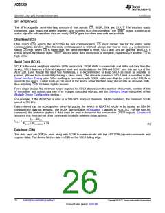
START Pin
or
or
START(1)
Opcode
STOP(1)
Opcode
DIN
tDR
tSETTLE
DRDY
(1) START and STOP opcode commands take effect on the seventh SCLK falling edge.
Figure 36. Continuous Conversion Mode
tSDSU
DRDY and DOUT
tDSHD
START Pin
or
STOP(1)
STOP(1)
STOP Opcode
(1) START and STOP commands take effect on the seventh SCLK falling edge at the end of the opcode transmission.
Figure 37. START to DRDY Timing
Table 9. Timing Characteristics for Figure 37(1)
SYMBOL
tSDSU
DESCRIPTION
MIN
16
UNIT
1/fCLK
1/fCLK
START pin low or STOP opcode to DRDY setup time to halt further
conversions
tDSHD
START pin low or STOP opcode to complete current conversion
16
(1) START and STOP commands take effect on the seventh SCLK falling edge at the end of the opcode transmission.
30
Submit Documentation Feedback
Copyright © 2012, Texas Instruments Incorporated
Product Folder Link(s): ADS1299

 TI [ TEXAS INSTRUMENTS ]