ADS1299
www.ti.com
SBAS499A –JULY 2012–REVISED AUGUST 2012
Reset (RESET)
There are two methods to reset the ADS1299: pull the RESET pin low, or send the RESET opcode command.
When using the RESET pin, take the pin low to force a reset. Make sure to follow the minimum pulse width
timing specifications before taking the RESET pin back high. The RESET command takes effect on the eighth
SCLK falling edge of the opcode command. On reset, 18 tCLK cycles are required to complete initialization of the
configuration registers to default states and start the conversion cycle. Note that an internal RESET is
automatically issued to the digital filter whenever the CONFIG1 register is set to a new value with a WREG
command.
START
The START pin must be set high or the START command sent to begin conversions. When START is low or if
the START command has not been sent, the device does not issue a DRDY signal (conversions are halted).
When using the START opcode to control conversions, hold the START pin low. The ADS1299 features two
modes to control conversions: continuous mode and single-shot mode. The mode is selected by SINGLE_SHOT
(bit 3 of the CONFIG4 register). In multiple device configurations, the START pin is used to synchronize devices
(see the Multiple Device Configuration subsection of the SPI Interface section for more details).
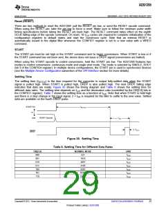
Settling Time
The settling time (tSETTLE) is the time required for the converter to output fully-settled data when the START
signal is pulled high. When START is pulled high, DRDY is also pulled high. The next DRDY falling edge
indicates that data are ready. Figure 35 shows the timing diagram and Table 8 shows the settling time for
different data rates. The settling time depends on fCLK and the decimation ratio (controlled by the DR[2:0] bits in
the CONFIG1 register). Table 7 shows the settling time as a function of tCLK. Note that when START is held high
and there is a step change in the input signal, 3 × tDR is required for the filter to settle to the new value. Settled
data are available on the fourth DRDY pulse.
tSETTLE
START Pin
or
START Opcode
DIN
tDR
4 / fCLK
DRDY
Figure 35. Settling Time
Table 8. Settling Time for Different Data Rates
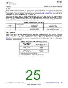
DR[2:0]
NORMAL MODE
521
UNIT
tCLK
tCLK
tCLK
tCLK
tCLK
tCLK
tCLK
000
001
010
011
100
101
110
1033
2057
4105
8201
16393
32777
Copyright © 2012, Texas Instruments Incorporated
Submit Documentation Feedback
29
Product Folder Link(s): ADS1299

 TI [ TEXAS INSTRUMENTS ]