Application Notes
AN1003
L
1
Ramp
Load
UJT Triggering Level
Cool
Hot
R
2
R
*
Pedestal
3
C
1
3.3 k
UJT Emitter Voltage
100
0
Time
Load
R
1
Q
AC
Input
1
D
1
D
D
D
2
1
R
R
6
2
"Gain"
C
C
*
2
R
3
1
HT-32
0.1 µF
100 V
R
R
Q
R
Q
2
Triac
7
8
3
120 V
(60 Hz)
D
5
D
6
D
3
4
1
Note: L and C form an
RFI filter that may be eliminated
* dv/dt snubber network
when required
R
Temp
1
1
5
C
1
T
R
4
T
1
AC
AC
Input
Voltage Current
Load
R
C , C
L
Q
1
1
1
3
1
R
R
R
R
= 2.2 k, 2 W
2
Q
Q
T
= 2N2646
= Q2010L5
= Dale PT 10-101
or equivalent
= 200 V Diode
= 20 V Zener
= 100 V Diode
= 0.1 µF, 30 V
,
1
3
4
1
2
1
= 2.2 k, 1/2 W
= Thermistor, approx. 5 k
at operating temperature
= 10 k Potentiometer
= 5 M Potentiometer
= 100 k, 1/2 W
120 V ac 12 A
60 Hz
250 k
500 k
0.1 µF 200 V 100 µH Q2015L9
0.1 µF 400 V 200 µH Q4004L4
R
R
R
R
D
D
D
C
5
6
7
8
1-4
240 V ac
50/60 Hz
3 A
5
6
1
= 1 k, 1/2 W
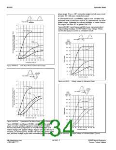
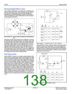
Figure AN1003.14 Single-time-constant Circuit for Incandescent Light
Dimming, Heat Control, and Motor Speed Control
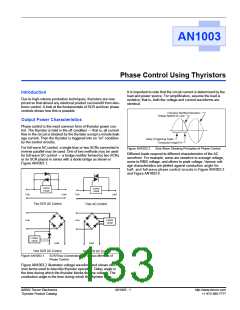
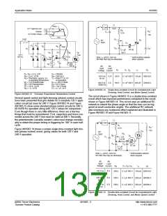
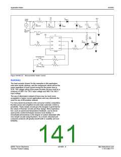
Figure AN1003.13 Precision Proportional Temperature Control
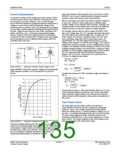
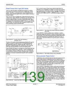
The circuit shown in Figure AN1003.15 is a double-time-constant
circuit which has improved performance compared to the circuit
shown in Figure AN1003.14. This circuit uses an additional RC
network to extend the phase angle so that the triac can be trig-
gered at small conduction angles. The additional RC network
also minimizes any hysteresis effect explained and illustrated in
Figure AN1003.10 and Figure AN1003.11.
Several speed control and light dimming (phase) control circuits
have been presented that give details for a complete 120 V appli-
cation circuit but none for 240 V. Figure AN1003.14 and Figure
AN1003.15 show some standard phase control circuits for 240 V,
60 Hz/50 Hz operation along with 120 V values for comparison.
Even though there is very little difference, there are a few key
things that must be remembered. First, capacitors and triacs con-
nected across the 240 V line must be rated at 400 V. Secondly,
the potentiometer (variable resistor) value must change consider-
ably to obtain the proper timing or triggering for 180° in each half-
cycle.
L
1
Load
R
1
R
*
4
3.3 k
Figure AN1003.14 shows a simple single-time-constant light dim-
mer (phase control) circuit, giving values for both 120 V and
240 V operation.
100
Q
1
AC
Input
R
3
R
2
D
1
C
15 k
1/2 W
1
C
C
2
C
*
3
4
HT-32
0.1 µF
100 V
Note: L and C form an
RFI filter that may be eliminated
* dv/dt snubber network
when required
1
1
AC
Input
AC
Load
Voltage
Current
C , C , C
1 2 4
R
L
1
Q
2
1
120 V ac
60 Hz
8 A
6 A
6 A
250 k
500 k
500 k
0.1 µF 200 V 100 µH Q2010L5
0.1 µF 400 V 200 µH Q4008L4
0.1 µF 400 V 200 µH Q4008L4
240 V ac
50 Hz
240 V ac
60 Hz
Figure AN1003.15 Double-time-constant Circuit for Incandescent Light
Dimming, Heat Control, and Motor Speed Control
©2002 Teccor Electronics
Thyristor Product Catalog
AN1003 - 5
http://www.teccor.com
+1 972-580-7777

 TECCOR [ TECCOR ELECTRONICS ]