AN1003
Application Notes
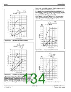
phase angle. Thus, a 180° conduction angle in a half-wave circuit
provides 0.5 x full-wave conduction power.
In a full-wave circuit, a conduction angle of 150° provides 97%
full power while a conduction angle of 30° provides only 3% of full
power control. Therefore, it is usually pointless to obtain conduc-
tion angles less than 30° or greater than 150°.
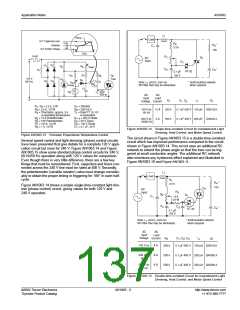
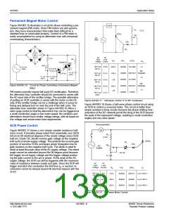
Figure AN1003.5 and Figure AN1003.6 give convenient direct
output voltage readings for 115 V/230 V input voltage. These
curves also apply to current in a resistive circuit.
HALF WAVE
Peak Voltage
θ
1.8
1.6
1.4
1.2
1.0
0.8
0.6
0.4
0.2
0
HALF WAVE
Input
Voltage
θ
RMS
230 V
115 V
360 180
320 160
280 140
240 120
200 100
160 80
120 60
80 40
Power
Peak Voltage
AVG
RMS
0
20 40 60 80 100 120 140 160 180
Conduction Angle (θ)
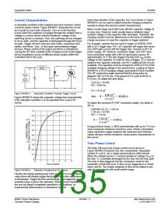
Figure AN1003.3
Half-Wave Phase Control (Sinusoidal)
AVG
40 20
θ
0
0
0
20 40 60 80 100 120 140 160 180
FULL WAVE
θ
Conduction Angle (θ)
1.8
1.6
1.4
1.2
1.0
0.8
0.6
0.4
0.2
0
Figure AN1003.5
Output Voltage of Half-wave Phase
Peak Voltage
θ
FULL WAVE
Input
Voltage
θ
RMS
230 V
115 V
360 180
320 160
280 140
240 120
200 100
160 80
120 60
80 40
Power
Peak Voltage
RMS
AVG
AVG
0
20 40 60 80 100 120 140 160 180
Conduction Angle (θ)
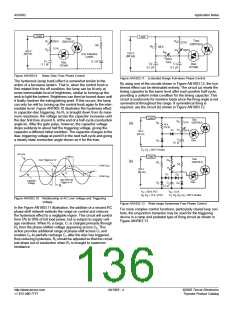
Figure AN1003.4
Symmetrical Full-Wave Phase Control (Sinusoidal)
40 20
Figure AN1003.3 and Figure AN1003.4 also show the relative
power curve for constant impedance loads such as heaters.
Because the relative impedance of incandescent lamps and
motors change with applied voltage, they do not follow this curve
precisely. To use the curves, find the full-wave rated power of the
load, and then multiply by the ratio associated with the specific
0
0
0
20 40 60 80 100 120 140 160 180
Conduction Angle (θ)
Figure AN1003.6
Output Voltage of Full-wave Phase Control
http://www.teccor.com
+1 972-580-7777
AN1003 - 2
©2002 Teccor Electronics
Thyristor Product Catalog

 TECCOR [ TECCOR ELECTRONICS ]