AN1003
AN10039
Phase Control Using Thyristors
It is important to note that the circuit current is determined by the
load and power source. For simplification, assume the load is
resistive; that is, both the voltage and current waveforms are
identical.
Introduction
Due to high-volume production techniques, thyristors are now
priced so that almost any electrical product can benefit from elec-
tronic control. A look at the fundamentals of SCR and triac phase
controls shows how this is possible.
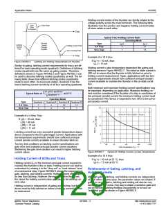
Full-wave Rectified Operation
Voltage Applied to Load
Output Power Characteristics
Phase control is the most common form of thyristor power con-
trol. The thyristor is held in the off condition — that is, all current
flow in the circuit is blocked by the thyristor except a minute leak-
age current. Then the thyristor is triggered into an “on” condition
by the control circuitry.
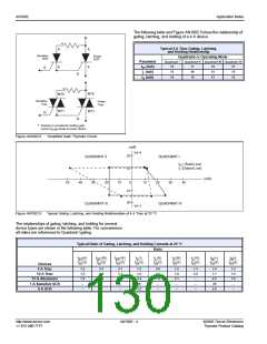
Delay (Triggering) Angle
Conduction Angle
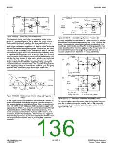
For full-wave AC control, a single triac or two SCRs connected in
inverse parallel may be used. One of two methods may be used
for full-wave DC control — a bridge rectifier formed by two SCRs
or an SCR placed in series with a diode bridge as shown in
Figure AN1003.1.
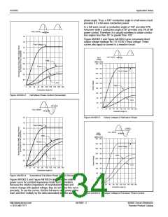
Figure AN1003.2
Sine Wave Showing Principles of Phase Control
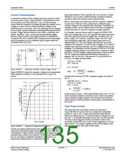
Different loads respond to different characteristics of the AC
waveform. For example, some are sensitive to average voltage,
some to RMS voltage, and others to peak voltage. Various volt-
age characteristics are plotted against conduction angle for
half- and full-wave phase control circuits in Figure AN1003.3
and Figure AN1003.4.
Control
Circuit
Control
Circuit
Line
Load
Line
Load
Two SCR AC Control
Triac AC Control
Line
Line
Control
Circuit
Control
Circuit
Load
Load
One SCR DC Control
Two SCR DC Control
Figure AN1003.1
SCR/Triac Connections for Various Methods of
Phase Control
Figure AN1003.2 illustrates voltage waveform and shows com-
mon terms used to describe thyristor operation. Delay angle is
the time during which the thyristor blocks the line voltage. The
conduction angle is the time during which the thyristor is on.
©2002 Teccor Electronics
Thyristor Product Catalog
AN1003 - 1
http://www.teccor.com
+1 972-580-7777

 TECCOR [ TECCOR ELECTRONICS ]