AN1003
Application Notes
C3
0.1 µF
R1
47
D1
1N4001
VDD
120 V ac
(High)
R2
1 M
RV1
Varistor
D1
1N4001
D3
1N5231
C1
220 µF
C2
0.01 µF
AC
(Return)
White
+5 V
U1
150 W
Lamp
VDD
VSS
GP0
GP1
GP2
Q1
L4008L5
GP5
GP4
GP3
R3
20 M
R6
470
12C508
Remote
Switch
Connector
R4
470
JP1
S1
S2
Dim
3
2
1
R5
470
Bright
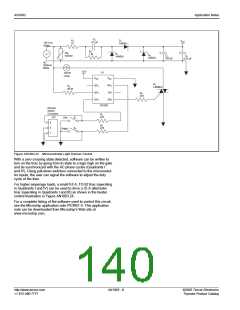
Figure AN1003.23 Microcontroller Light Dimmer Control
With a zero crossing state detected, software can be written to
turn on the triac by going from tri-state to a logic high on the gate
and be synchronized with the AC phase cycles (Quadrants I
and IV). Using pull-down switches connected to the microcontol-
ler inputs, the user can signal the software to adjust the duty
cycle of the triac.
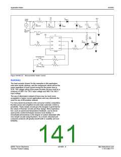
For higher amperage loads, a small 0.8 A, TO-92 triac (operating
in Quadrants I and IV) can be used to drive a 25 A alternistor
triac (operating in Quadrants I and III) as shown in the heater
control illustration in Figure AN1003.24.
For a complete listing of the software used to control this circuit,
see the Microchip application note PICREF-4. This application
note can be downloaded from Microchip's Web site at
www.microchip.com.
http://www.teccor.com
+1 972-580-7777
AN1003 - 8
©2002 Teccor Electronics
Thyristor Product Catalog

 TECCOR [ TECCOR ELECTRONICS ]