Application Notes
AN1003
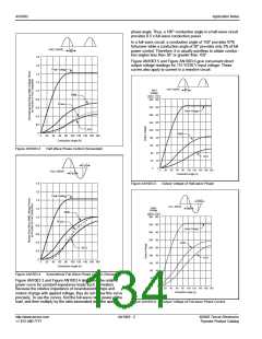
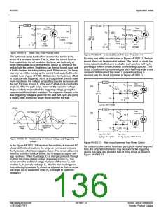
Upon final selection of the capacitor, the curve shown in Figure
AN1003.8 can be used in determining the charging resistance
needed to obtain the desired control characteristics.
Many circuits begin each half-cycle with the capacitor voltage at
or near zero. However, most circuits leave a relatively large
residual voltage on the capacitor after discharge. Therefore, the
charging resistor must be determined on the basis of additional
charge necessary to raise the capacitor to trigger potential.
For example, assume that we want to trigger an S2010L SCR
with a 32 V trigger diac. A 0.1 µF capacitor will supply the neces-
sary SCR gate current with the trigger diac. Assume a 50 V dc
power supply, 30° minimum conduction angle, and 150° maxi-
mum conduction angle with a 60 Hz input power source. At
approximately 32 V, the diac triggers leaving 0.66 VBO of diac
voltage on the capacitor. In order for diac to trigger, 22 V must be
added to the capacitor potential, and 40 V additional (50-10) are
available. The capacitor must be charged to 22/40 or 0.55 of the
available charging voltage in the desired time. Looking at Figure
AN1003.8, 0.55 of charging voltage represents 0.8 time constant.
The 30° conduction angle required that the firing pulse be
delayed 150° or 6.92 ms. (The period of 1/2 cycle at 60 Hz is
8.33 ms.) To obtain this time delay:
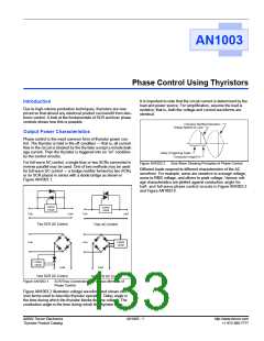
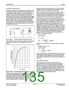
Control Characteristics
A relaxation oscillator is the simplest and most common control
circuit for phase control. Figure AN1003.7 illustrates this circuit
as it would be used with a thyristor. Turn-on of the thyristor
occurs when the capacitor is charged through the resistor from a
voltage or current source until the breakover voltage of the
switching device is reached. Then, the switching device changes
to its on state, and the capacitor is discharged through the thyris-
tor gate. Trigger devices used are neon bulbs, unijunction tran-
sistors, and three-, four-, or five-layer semiconductor trigger
devices. Phase control of the output waveform is obtained by
varying the RC time constant of the charging circuit so the trigger
device breakdown occurs at different phase angles within the
controlled half or full cycle.
Switching
Device
R
Voltage
or
SCR
Triac
Current
Source
C
6.92 ms = 0.8 RC
RC = 8.68 ms
if C = 0.10 µF
Figure AN1003.7
Relaxation Oscillator Thyristor Trigger Circuit
8.68×10⁻³
then, R = ------------------------- = 86,000 Ω
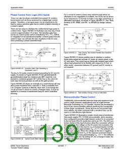
Figure AN1003.8 shows the capacitor voltage-time characteristic
if the relaxation oscillator is to be operated from a pure DC
source.
0.1×10⁻⁶
To obtain the minimum R (150° conduction angle), the delay is
30° or
(30/180) x 8.33 = 1.39 ms
1.39 ms = 0.8 RC
RC = 1.74 ms
1.0
0.9
0.8
0.7
0.6
0.5
0.4
0.3
0.2
0.1
0
1.74×10⁻³
R = -------------------------- = 17,400 Ω
0.1×10⁻⁶
Using practical values, a 100 k potentiometer with up to 17 k min-
imum (residual) resistance should be used. Similar calculations
using conduction angles between the maximum and minimum
values will give control resistance versus power characteristic of
this circuit.
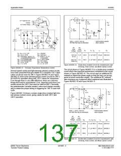
Triac Phase Control
The basic full-wave triac phase control circuit shown in
Figure AN1003.9 requires only four components. Adjustable
resistor R1 and C1 are a single-element phase-shift network.
When the voltage across C1 reaches breakover voltage (VBO) of
the diac, C1 is partially discharged by the diac into the triac gate.
The triac is then triggered into the conduction mode for the
remainder of that half-cycle. In this circuit, triggering is in Quad-
rants I and III. The unique simplicity of this circuit makes it suit-
able for applications with small control range.
0
1
2
3
4
5
6
Time Constants
Figure AN1003.8
Capacitor Charging from DC Source
Usually, the design starting point is the selection of a capacitance
value which will reliably trigger the thyristor when the capacitance
is discharged. Trigger devices and thyristor gate triggering char-
acteristics play a part in the selection. All the device characteris-
tics are not always completely specified in applications, so
experimental determination is sometimes needed.
©2002 Teccor Electronics
Thyristor Product Catalog
AN1003 - 3
http://www.teccor.com
+1 972-580-7777

 TECCOR [ TECCOR ELECTRONICS ]