Application Notes
AN1003
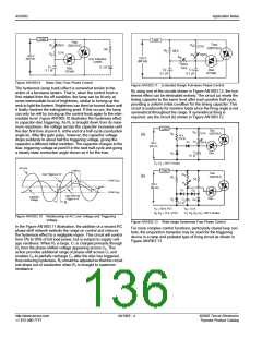
For a circuit to control a heavy-duty inductive load where an
Phase Control from Logic (DC) Inputs
alternistor is not compatible or available, two SCRs can be driven
by an inexpensive TO-92 triac to make a very high current triac or
alternistor equivalent, as shown in Figure AN1003.21. See ”Rela-
tionship of IAV, IRMS, and IPK’ in AN1009 for design calcula-
tions.
Triacs can also be phase-controlled from pulsed DC unidirec-
tional inputs such as those produced by a digital logic control
system. Therefore, a microprocessor can be interfaced to AC
load by using a sensitive gate triac to control a lamp's intensity or
a motor's speed.
Hot
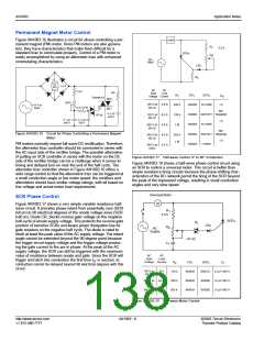
There are two ways to interface the unidirectional logic pulse to
control a triac. Figure AN1003.19 illustrates one easy way if load
current is approximately 5 A or less. The sensitive gate triac
serves as a direct power switch controlled by HTL, TTL, CMOS,
or integrated circuit operational amplifier. A timed pulse from the
system's logic can activate the triac anywhere in the AC sine-
wave producing a phase-controlled load.
Load
MT
2
Non-sensitive
Gate SCRs
Triac
A
K
K
G
A
Gate Pulse
Input
G
G
OR
MT
1
Hot
Load
V
= 15 V
DC
DD
MT
MT
Neutral
2
V
Sensitive Gate
Triac
DD
OV
Figure AN1003.21 Triac Driving Two Inverse Parallel Non-Sensitive
Gate SCRs
120 V
60 Hz
1
16
Figure AN1003.22 shows another way to interface a unidirec-
tional pulse signal and activate AC loads at various points in the
AC sine wave. This circuit has an electrically-isolated input which
allows load placement to be flexible with respect to AC line. In
other words, connection between DC ground and AC neutral is
not required.
G
8
Neutral
Figure AN1003.19 Sensitive Gate Triac Operating in
Quadrants I and IV
The key to DC pulse control is correct grounding for DC and AC
supply. As shown in Figure AN1003.19, DC ground and AC
ground/neutral must be common plus MT1 must be con-
nected to common ground. MT1 of the triac is the return for
both main terminal junctions as well as the gate junction.
Load
Hot
R
in
100
100
6
4
1
2
Timed
Input
Pulse
120 V
60 Hz
MT
MT
2
0.1 µF
250 V
C
1
Triac or
Alternistor
1
G
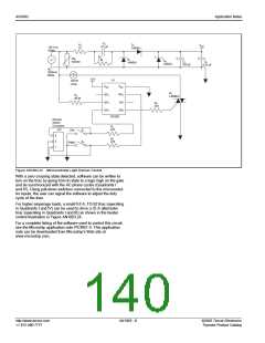
Figure AN1003.20 shows an example of a unidirectional (all neg-
ative) pulse furnished from a special I.C. that is available from
LSI Computer Systems in Melville, New York. Even though the
circuit and load is shown to control a Halogen lamp, it could be
applied to a common incandescent lamp for touch-controlled
dimming.
Neutral
Load could be here
instead of upper location
Figure AN1003.22 Opto-isolator Driving a Triac or Alternistor
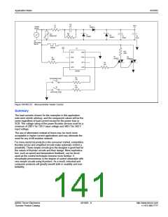
Microcontroller Phase Control
L
Traditionally, microcontrollers were too large and expensive to be
used in small consumer applications such as a light dimmer.
Microchip Technology Inc. of Chandler, Arizona has developed a
line of 8-pin microcontrollers without sacrificing the functionality
of their larger counterparts. These devices do not provide high
drive outputs, but when combined with a sensitive triac can be
used in a cost-effective light dimmer.
Figure AN1003.23 illustrates a simple circuit using a transformer-
less power supply, PIC 12C508 microcontroller, and a sensitive
triac configured to provide a light dimmer control. R3 is connected
to the hot lead of the AC power line and to pin GP4. The ESD pro-
tection diodes of the input structure allow this connection without
damage. When the voltage on the AC power line is positive, the
protection diode form the input to VDD is forward biased, and the
input buffer will see approximately VDD + 0.7 V. The software will
read this pin as high. When the voltage on the line is negative,
the protection diode from VSS to the input pin is forward biased,
and the input buffer sees approximately VSS - 0.7 V. The software
will read the pin as low. By polling GP4 for a change in state, the
software can detect zero crossing.
R
3
G
MT1
MT2
+
C
T
Z
5
115 V ac
220 V ac
D
1
L
R
R
6
5
Touch
Plate
C
1
8
7
6
5
C
TRIG VSS
EXT SENS
2
LS7631 / LS7632
R
1
VDD MODE CAP SYNC
R
4
R
2
1
2
4
3
N
NOTE: As a precaution,
transformer should have
thermal protection.
C
C
4
3
Halogen
Lamp
115 V ac
220 V ac
C
C
C
C
C
R
R
= 0.15 µF, 200 V
= 0.22 µF, 200 V
= 0.02 µF, 12 V
= 0.002 µF, 12 V
= 100 µF, 12 V
= 270, ¼ W
R
R
= 62, ¼ W
= 1 M to 5 M, ¼ W
(Selected for sensitivity)
, R = 4.7 M, ¼ W
= 1N4148
Z = 5.6 V, 1 W Zener
T = Q4006LH4 Alternistor
L = 100 µH (RFI Filter)
C
= 0.15 µF, 400 V
= 0.1 µF, 400 V
= 0.02 µF, 12 V
= 0.002 µF, 12 V
= 100 µF, 12 V
= 1 k, ¼ W
R
R
= 62, ¼ W
= 1 M to 5 M, ¼ W
(Selected for sensitivity)
, R = 4.7 M, ¼ W
1
2
3
4
5
1
2
3
4
1
2
3
4
5
1
2
3
4
C
C
C
C
R
R
R
D
R
D
5
1
6
5
1
6
= 1N4148
Z = 5.6 V, 1 W Zener
T = Q6006LH4 Alternistor
L = 200 µH (RFI Filter)
= 680 k, ¼ W
= 1.5 M, ¼ W
Figure AN1003.20 Typical Touch Plate Halogen Lamp Dimmer
©2002 Teccor Electronics
Thyristor Product Catalog
AN1003 - 7
http://www.teccor.com
+1 972-580-7777

 TECCOR [ TECCOR ELECTRONICS ]