AN1003
Application Notes
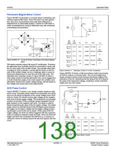
Permanent Magnet Motor Control
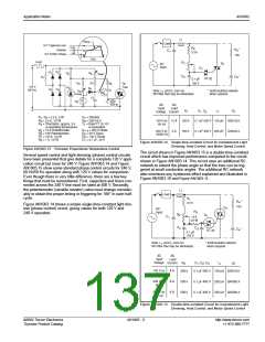
Figure AN1003.16 illustrates a circuit for phase controlling a per-
manent magnet (PM) motor. Since PM motors are also genera-
tors, they have characteristics that make them difficult for a
standard triac to commutate properly. Control of a PM motor is
easily accomplished by using an alternistor triac with enhanced
commutating characteristics.
Load
R
1
2.2 k
SCR
1
R
2
AC
Input
CR
1
R
3
+
DC
1.5 A
MTR
AC
Input
Voltage Current
AC
Load
3.3 k
-
100
MT2
CR
R
SCR
1
R
3
1
2
Q4006LH4
250 k
120 V ac 0.8 A
60 Hz
500 k
100 k
1 M
IN4003
EC103B
1 k
115 V ac
Input
15 k 1/2 W
G
MT1
Not
0.1 µF
400 V
IN4003 S2010F1 Required
120 V ac 8.5 A
60 Hz
HT-32
0.1 µF
400 V
0.1 µF
100 V
1 k
IN4004
EC103D
240 V ac 0.8 A
60 Hz
Not
Figure AN1003.16 Circuit for Phase Controlling a Permanent Magnet
Motor
IN4004 S4010F1 Required
240 V ac 8.5 A
60 Hz
250 k
1 M
1 k
IN4004
T106D1
PM motors normally require full-wave DC rectification. Therefore,
the alternistor triac controller should be connected in series with
the AC input side of the rectifier bridge. The possible alternative
of putting an SCR controller in series with the motor on the DC
side of the rectifier bridge can be a challenge when it comes to
timing and delayed turn-on near the end of the half cycle. The
alternistor triac controller shown in Figure AN1003.16 offers a
wide range control so that the alternistror triac can be triggered at
a small conduction angle or low motor speed; the rectifiers and
alternistors should have similar voltage ratings, with all based on
line voltage and actual motor load requirements.
240 V ac 2.5 A
50Hz
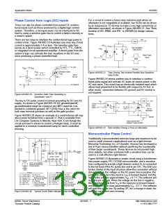
Figure AN1003.17 Half-wave Control, 0° to 90° Conduction
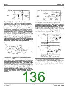
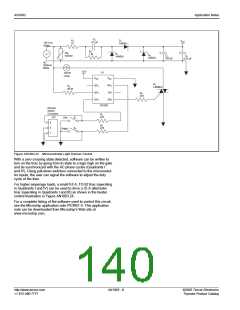
Figure AN1003.18 shows a half-wave phase control circuit using
an SCR to control a universal motor. This circuit is better than
simple resistance firing circuits because the phase-shifting char-
acteristics of the RC network permit the firing of the SCR beyond
the peak of the impressed voltage, resulting in small conduction
angles and very slow speed.
Universal Motor
M
SCR Phase Control
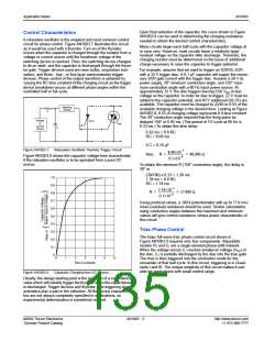
Figure AN1003.17 shows a very simple variable resistance half-
wave circuit. It provides phase retard from essentially zero (SCR
full on) to 90 electrical degrees of the anode voltage wave (SCR
half on). Diode CR1 blocks reverse gate voltage on the negative
half-cycle of anode supply voltage. This protects the reverse gate
junction of sensitive SCRs and keeps power dissipation low for
gate resistors on the negative half cycle. The diode is rated to
block at least the peak value of the AC supply voltage. The retard
angle cannot be extended beyond the 90-degree point because
the trigger circuit supply voltage and the trigger voltage produc-
ing the gate current to fire are in phase. At the peak of the AC
supply voltage, the SCR can still be triggered with the maximum
value of resistance between anode and gate. Since the SCR will
trigger and latch into conduction the first time IGT is reached, its
conduction cannot be delayed beyond 90 electrical degrees with this
circuit.
R
1
2
1
3.3 k
SCR
1
D
1
CR
1
R
C
AC
Supply
HT-32
AC
Input
AC
Load
Voltage Current
R
CR
SCR
C
1
2
1
1
120 V ac
60 Hz
8 A
150 k
200 k
200 k
IN4003
IN4004
IN4004
S2015L 0.1µF 200 V
S4008L 0.1µF 400 V
S4008L 0.1µF 400 V
240 V ac 6.5 A
60 Hz
240 V ac 6.5 A
50 Hz
Figure AN1003.18 Half-wave Motor Control
http://www.teccor.com
+1 972-580-7777
AN1003 - 6
©2002 Teccor Electronics
Thyristor Product Catalog

 TECCOR [ TECCOR ELECTRONICS ]