ICM-20690
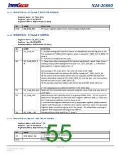
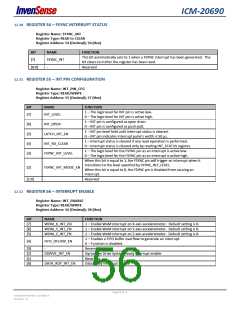
12.30 REGISTER 54 – FSYNC INTERRUPT STATUS
Register Name: FSYNC_INT
Register Type: READ to CLEAR
Register Address: 54 (Decimal); 36 (Hex)
BIT
[7]
NAME
FUNCTION
This bit automatically sets to 1 when a FSYNC interrupt has been generated. The
bit clears to 0 after the register has been read.
Reserved
FSYNC_INT
-
[6:0]
12.31 REGISTER 55 – INT PIN CONFIGURATION
Register Name: INT_PIN_CFG
Register Type: READ/WRITE
Register Address: 55 (Decimal); 37 (Hex)
BIT
NAME
FUNCTION
1 – The logic level for INT pin is active low.
0 – The logic level for INT pin is active high.
[7]
INT_LEVEL
1 – INT pin is configured as open drain.
0 – INT pin is configured as push-pull.
[6]
[5]
[4]
[3]
INT_OPEN
1 – INT pin level held until interrupt status is cleared.
0 – INT pin indicates interrupt pulse’s width is 50 µs.
1 – Interrupt status is cleared if any read operation is performed.
0 – Interrupt status is cleared only by reading INT_STATUS register.
1 – The logic level for the FSYNC pin as an interrupt is active low.
0 – The logic level for the FSYNC pin as an interrupt is active high.
When this bit is equal to 1, the FSYNC pin will trigger an interrupt when it
transitions to the level specified by FSYNC_INT_LEVEL.
When this bit is equal to 0, the FSYNC pin is disabled from causing an
interrupt.
LATCH_INT_EN
INT_RD_CLEAR
FSYNC_INT_LEVEL
[2]
FSYNC_INT_MODE_EN
-
[1:0]
Reserved
12.32 REGISTER 56 – INTERRUPT ENABLE
Register Name: INT_ENABLE
Register Type: READ/WRITE
Register Address: 56 (Decimal); 38 (Hex)
BIT
[7]
[6]
[5]
NAME
FUNCTION
WOM_X_INT_EN
WOM_Y_INT_EN
WOM_Z_INT_EN
1 – Enable WoM interrupt on X-axis accelerometer. Default setting is 0.
1 – Enable WoM interrupt on Y-axis accelerometer. Default setting is 0.
1 – Enable WoM interrupt on Z-axis accelerometer. Default setting is 0.
1 – Enables a FIFO buffer overflow to generate an interrupt.
0 – Function is disabled.
[4]
FIFO_OFLOW_EN
[3]
[2]
[1]
[0]
-
Reserved
GDRIVE_INT_EN
-
DATA_RDY_INT_EN
Gyroscope Drive System Ready interrupt enable
Reserved
Data ready interrupt enable
Page 56 of 76
Document Number: DS-000178
Revision: 1.0

 TDK [ TDK ELECTRONICS ]