UPSD3212C, UPSD3212CV
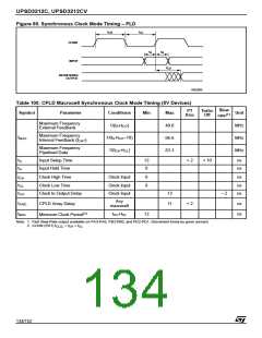
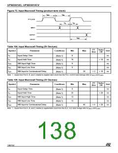
Figure 69. Synchronous Clock Mode Timing – PLD
t
t
CL
CH
CLKIN
INPUT
t
S
t
H
t
CO
REGISTERED
OUTPUT
AI02860
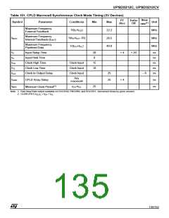
Table 100. CPLD Macrocell Synchronous Clock Mode Timing (5V Devices)
Slew
PT
Aloc
Turbo
Off
Symbol
Parameter
Conditions
Min
Max
40.0
66.6
83.3
Unit
MHz
MHz
MHz
(1)
rate
Maximum Frequency
External Feedback
1/(t +t
)
CO
S
Maximum Frequency
f
1/(t +t –10)
S CO
MAX
Internal Feedback (f
)
CNT
Maximum Frequency
Pipelined Data
1/(t +t
)
CH CL
t
t
Input Setup Time
Input Hold Time
12
0
+ 2
+ 10
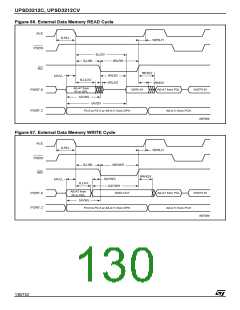
ns
ns
S
H
Clock High Time
Clock Input
Clock Input
Clock Input
6
6
ns
ns
ns
t
t
t
CH
CL
Clock Low Time
Clock to Output Delay
13
11
– 2
CO
Any
macrocell
t
t
CPLD Array Delay
+ 2
ns
ns
ARD
(2)
t +t
CH CL
12
MIN
Minimum Clock Period
Note: 1. Fast Slew Rate output available on PA3-PA0, PB3-PB0, and PD2-PD1. Decrement times by given amount.
2. CLKIN (PD1) t = t + t
.
CL
CLCL
CH
134/152

 STMICROELECTRONICS [ ST ]