Description
STM32F405xx, STM32F407xx
Standby mode, the SRAM and register contents are lost except for registers in the
backup domain and the backup SRAM when selected.
The device exits the Standby mode when an external reset (NRST pin), an IWDG reset,
a rising edge on the WKUP pin, or an RTC alarm / wakeup / tamper /time stamp event
occurs.
The standby mode is not supported when the embedded voltage regulator is bypassed
and the V domain is controlled by an external power.
12
2.2.20
V
operation
BAT
The V
pin allows to power the device V
domain from an external battery, an external
BAT
BAT
supercapacitor, or from V when no external battery and an external supercapacitor are
DD
present.
V
operation is activated when V is not present.
DD
BAT
The V
pin supplies the RTC, the backup registers and the backup SRAM.
BAT
Note:
When the microcontroller is supplied from V , external interrupts and RTC alarm/events
BAT
do not exit it from V
operation.
BAT
When PDR_ON pin is not connected to V (internal reset OFF), the V
functionality is no
BAT
DD
more available and V
pin should be connected to V
.
BAT
DD
2.2.21
Timers and watchdogs
The STM32F405xx and STM32F407xx devices include two advanced-control timers, eight
general-purpose timers, two basic timers and two watchdog timers.
All timer counters can be frozen in debug mode.
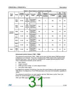
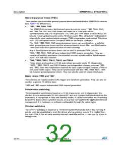
Table 4 compares the features of the advanced-control, general-purpose and basic timers.
Table 4. Timer feature comparison
DMA
request
generatio
n
Max
Max
Counter
Timer resolutio
n
Capture/
compare
channels
Timer
type
Counter Prescaler
Complementar interface timer
type
factor
y output
clock
(MHz) (MHz)
clock
Up,
Down,
Up/dow
n
Anyinteger
between 1
and 65536
Advanced TIM1,
-control TIM8
16-bit
Yes
4
Yes
84
168
30/185
DocID022152 Rev 4

 STMICROELECTRONICS [ ST ]