Description
STM32F405xx, STM32F407xx
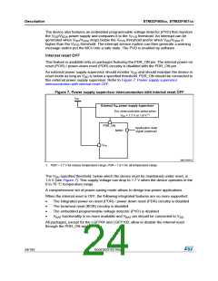
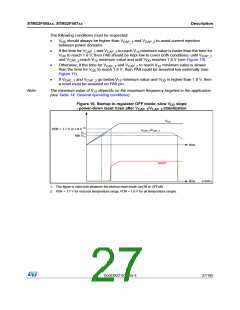
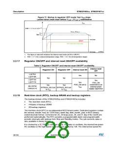
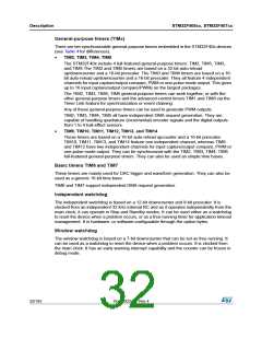
Figure 11. Startup in regulator OFF mode: fast V slope
DD
- power-down reset risen before V
/V
stabilization
CAP_1 CAP_2
VDD
PDR = 1.7 V or 1.8 V (2)
VCAP_1/VCAP_2
V12
Min V12
time
time
NRST
PA0 asserted externally
ai18492d
1. This figure is valid both whatever the internal reset mode (onON or offOFF).
2. PDR = 1.7 V for a reduced temperature range; PDR = 1.8 V for all temperature ranges.
2.2.17
Regulator ON/OFF and internal reset ON/OFF availability
Table 3. Regulator ON/OFF and internal reset ON/OFF availability
Internal reset
Regulator ON
Regulator OFF Internal reset ON
OFF
LQFP64
Yes
No
LQFP100
Yes
Yes
No
LQFP144
LQFP176
Yes
Yes
PDR_ON
PDR_ON set to
VDD
connected to an
external power
supply supervisor
Yes
WLCSP90
UFBGA176
BYPASS_REGset BYPASS_REGset
to VSS to VDD
2.2.18
Real-time clock (RTC), backup SRAM and backup registers
The backup domain of the STM32F405xx and STM32F407xx includes:
•
•
•
The real-time clock (RTC)
4 Kbytes of backup SRAM
20 backup registers
The real-time clock (RTC) is an independent BCD timer/counter. Dedicated registers contain
the second, minute, hour (in 12/24 hour), week day, date, month, year, in BCD (binary-
coded decimal) format. Correction for 28, 29 (leap year), 30, and 31 day of the month are
performed automatically. The RTC provides a programmable alarm and programmable
periodic interrupts with wakeup from Stop and Standby modes. The sub-seconds value is
also available in binary format.
It is clocked by a 32.768 kHz external crystal, resonator or oscillator, the internal low-power
RC oscillator or the high-speed external clock divided by 128. The internal low-speed RC
28/185
DocID022152 Rev 4

 STMICROELECTRONICS [ ST ]