J1850 Byte Level Protocol Decoder (JBLPD)
J1850 BYTE LEVEL PROTOCOL DECODER (Cont’d)
Bit 7:4 = MLC[3:0] Message Length Count.
Message Length Count bits 3 to 0 are written when
the program writes one of the IFR opcodes. Upon
detection of the EOD symbol which delineates the
body of a frame from the IFR portion of the frame,
the received byte counter is compared against the
count contained in MLC[3:0]. If they match, then
the IFR will be transmitted. If they do not match,
then the TRA bit in the ERROR register is set and
no transmit attempt occurs.
MSG, Message Byte Opcode.
The Message byte opcode is set when the user
program wants to initiate or continue transmitting
the body of a message out the VPWO pin.
The body of a message is the string of data bytes
following an SOF symbol, but before the first EOD
symbol in a frame. If the J1850 bus is in an idle
condition when the opcode is written, an SOF
symbol is transmitted out the VPWO pin immedi-
ately before it transmits the data contained in TX-
DATA. If the JBLPD is not in idle and the J1850
transmitter has not been locked out by loss of arbi-
tration, then the TXDATA byte is transferred to the
serial output shift register for transmission immedi-
ately on completion of any previously transmitted
data. The final byte of a message string is not
transmitted using the MSG opcode (use the
MSG+CRC opcode).
– While NFL=0, an MCL[3:0] decimal value be-
tween 1 and 11 is considered valid. MCL[3:0]
values of 12, 13, 14, 15 are considered invalid
and will set the Transmit Request Aborted
(TRA) bit in the ERROR register.
– While NFL=1, an MCL[3:0] value between 1 and
15 is considered valid.
– For NFL=1 or 0, MCL[3:0] bits are don’t care dur-
ing a MSG or MSG+CRC opcode write.
Special Conditions for MSG Transmit:
– 1) A MSG cannot be queued on top of an execut-
ing IFR3 opcode. If so, then TRA is set, and
TDUF will get set because the transmit state
machine will be expecting more data, then the
inverted CRC is appended to this frame. Also,
no message byte will be sent on the next frame.
– If writing an IFR opcode and MCL[3:0]=0000,
then the message length count check is ignored
(i.e. MLC=Count is disabled), and the IFR is en-
abled only on a correct CRC and a valid EOD
symbol assuming no other error conditions
(IFD, IBD, RBRK) appear.
– 2) If NFL = 0 and an MSG queued without CRC
on Received Byte Count for this frame=10 will
trigger the TRA to get set, and TDUF will get set
because the state machine will be expecting
more data and the transmit machine will send
the inverted CRC after the byte which is pres-
ently transmitting. Also, no message byte will be
sent on the next frame.
Bit 3 = Reserved.
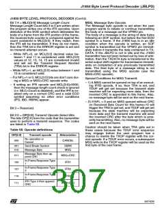
Bit 2:0 = OP[2:0] Transmit Opcode Select Bits.
The bits OP[2:0] form the code that the transmitter
uses to perform a transmit sequence. The codes
are listed in Table 58.
Caution should be taken when TRA gets set in
these cases because the TDUF error sequence
may engage before the user program has a
chance to rewrite the TXOP register with the cor-
rect opcode. If a TDUF error occurs, a subsequent
MSG write to the TXOP register will be used as the
first byte of the next frame.
Table 58. Opcode definitions
OP[2:0]
Transmit opcode
Abbreviation
No operation or
Cancel
000
CANCEL
001
010
Send Break Symbol
Message Byte
SBRK
MSG
Message Byte then ap-
pend CRC
011
100
101
110
111
MSG+CRC
IFR1
In-Frame Response Type
1
In-Frame Response Type
2
IFR2
In-Frame Response Type
3
IFR3
IFR Type 3 then append
CRC
IFR3+CRC
307/426
9

 STMICROELECTRONICS [ ST ]