J1850 Byte Level Protocol Decoder (JBLPD)
J1850 BYTE LEVEL PROTOCOL DECODER (Cont’d)
Bit 3 = RDT Receive Data Type.
The RDT bit indicates the type of data which is in
the RXDATA register: message byte or IFR byte.
Any byte received after an SOF but before an
EODM is considered a message byte type. Any
byte received after an SOF, EODM and NBx is an
IFR type.
RDT gets set or cleared at the same time that
RDRF gets set.
RDT is cleared on reset or while CONTROL.JE is
reset, or while CONTROL.JDIS bit is set.
0: Last RXDATA byte was a message type byte
1: Last RXDATA byte was a IRF type byte
Bit 0 = IDLE Idle Bus Flag
IDLE is set when the JBLPD decoded VPWI pin
recognized an IFS symbol. That is, an idle bus is
when the bus has been in a passive state for long-
er that the Tv6 symbol time. The IDLE flag will re-
main set as long as the decoded VPWI pin is pas-
sive. IDLE is cleared when the decoded VPWI pin
transitions to an active state.
Note that if the VPWI pin remains in a passive
state after JE is set, then the IDLE bit may go high
sometime before a Tv6 symbol is timed on VPWI
(since VPWI timers may be active when JE is
clear).
IDLE is cleared on reset or while the CON-
TROL.JDIS bit is set.
Bit 2 = EODM End of Data Minimum Flag.
The EODM flag is set when the JBLPD decoded
VPWI pin has been in a passive state for longer
that the minimum Tv3 symbol time unless the
EODM is inhibited by a sleep, filter or CRCE, IBD,
IFD or RBRK error condition during a frame.
EODM bit does not get set when in the sleep mode
or when a message is filtered.
The EODM bit can be cleared by software writing a
logic “zero” in the EODM position. EODM is
cleared on reset, while CONTROL.JE is reset or
while CONTROL.JDIS bit is set.
0: J1850 bus not in idle state
1: J1850 bus in idle state
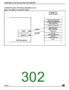
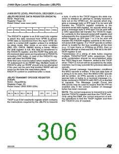
JBLPD TRANSMIT DATA REGISTER (TXDATA)
R241- Read/Write
Register Page: 23
Reset Value: xxxx xxxx (xxh)
7
0
TXD7 TXD6 TXD5 TXD4 TXD3 TXD2 TXD1 TXD0
If the EODM_M bit of the IMR register is set, when
this bit is set an interrupt request occurs.
0: No EOD symbol detected
The TXDATA register is an eight bits read/write
register in which the data to be transmitted must
be placed. A write to TXDATA merely enters a
byte into the register. To initiate an attempt to
transmit the data, the TXOP register must also be
written. When the TXOP write occurs, the TRDY
flag is cleared. While the TRDY bit is clear, the
data is still in the TXDATA register, so writes to the
TXDATA register with TRDY clear will overwrite
existing TXDATA. When the TXDATA is trans-
ferred to the shift register, the TRDY bit is set
again.
1: EOD symbol detected
Note: The EODM bit is not an error flag. It means
that the minimum time related to the passive Tv3
symbol is passed.
Bit 1 = EOFM End of Frame Minimum Flag.
The EOFM flag is set when the JBLPD decoded
VPWI pin has been in a passive state for longer
that the minimum Tv4 symbol time. EOFM will still
get set at the end of filtered frames or frames
where sleep mode was invoked. Consequently,
multiple EOFM flags may be encountered be-
tween frames of interest.
The EOFM bit can be cleared by software writing a
logic “zero” in the EOFM position. EOFM is
cleared on reset, while CONTROL.JE is reset or
while CONTROL.JDIS bit is set.
Reads of the TXDATA register will always return
the last byte written.
TXDATA contents are undefined after a reset.
Note: The correct sequence to transmit is to write
first the TXDATA register (if datum is needed) and
then the TXOP one.
Only using the DMA, the correct sequence of writ-
ing operations is first the TXOP register and then
the TXDATA one (if needed).
If the EOFM_M bit of the IMR register is set, when
this bit is set an interrupt request occurs.
0: No EOF symbol detected
1: EOF symbol detected
Note: The EOFM bit is not an error flag. It means
that the minimum time related to the passive Tv4
symbol is passed.
305/426
9

 STMICROELECTRONICS [ ST ]