I2C BUS INTERFACE
2
I C BUS INTERFACE (Cont’d)
2
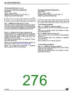
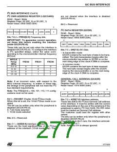
I C OWN ADDRESS REGISTER 2 (I2COAR2)
are not cleared when the interface is disabled
(I2CCR.PE=0).
R245 - Read / Write
Register Page: 20 (I2C_0) or 22 (I2C_1)
Reset Value: 0000 0000 (00h)
Bit 0 = Reserved.
7
0
2
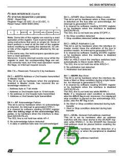
I C DATA REGISTER (I2CDR)
FREQ1 FREQ0 EN10BIT FREQ2
0
ADD9 ADD8
0
R246 - Read / Write
Register Page: 20 (I2C_0) or 22 (I2C_1)
Reset Value: 0000 0000 (00h)
Bits 7:6,4 = FREQ[2:0] Frequency bits.
IMPORTANT: To guarantee correct operation,
set these bits before enabling the interface
(while I2CCR.PE=0).
7
0
DR7 DR6 DR5 DR4 DR3 DR2 DR1 DR0
These bits can be set only when the interface is
disabled (I2CCR.PE=0). To configure the interface
Bits 7:0 = DR[7:0] I2C Data.
2
to I C specified delays, select the value corre-
– In transmitter mode:
sponding to the microcontroller internal frequency
INTCLK.
I2CDR contains the next byte of data to be trans-
mitted. The byte transmission begins after the
microcontroller has written in I2CDR or on the
next rising edge of the clock if DMA is complete.
INTCLK
Range
(MHz)
FREQ2
FREQ1
FREQ0
– In receiver mode:
2.5 - 6
6- 10
0
0
0
0
0
0
1
1
0
1
0
1
I2CDR contains the last byte of data received.
The next byte receipt begins after the I2CDR
read by the microcontroller or on the next rising
edge of the clock if DMA is complete.
10- 14
14 - 24
GENERAL CALL ADDRESS (I2CADR)
R247 - Read / Write
Register Page: 20 (I2C_0) or 22 (I2C_1)
Reset Value: 1010 0000 (A0h)
Note: If an incorrect value, with respect to the
MCU internal frequency, is written in these bits,
2
the timings of the peripheral will not meet the I C
bus standard requirements.
7
0
Note: The FREQ[2:0] = 100, 101, 110, 111 config-
urations must not be used.
ADR7 ADR6 ADR5 ADR4 ADR3 ADR2 ADR1 ADR0
2
2
Bit 5 = EN10BIT Enable 10-bit I Cbus mode.
Bits 7:0 = ADR[7:0] Interface address.
2
When this bit is set, the 10-bit I Cbus mode is en-
These bits define the I Cbus General Call address
abled.
of the interface. It must be written with the correct
value depending on the use of the peripheral.If the
This bit can be written only when the peripheral is
disabled (I2CCR.PE=0).
0: 7-bit mode selected
2
peripheral is used in I C bus mode, the 00h value
must be loaded as General Call address.
The customer could load the register with other
values.
1: 10-bit mode selected
The bits can be written only when the peripheral is
disabled (I2CCR.PE=0)
Bits 4:3 = Reserved.
The ADR0 bit is don’t care; the interface acknowl-
edges either 0 or 1.
Note: Address 01h is always ignored.
Bits 2:1 = ADD[9:8] Interface address.
2
These are the most significant bits of the I Cbus
address of the interface (10-bit mode only). They
277/426
9

 STMICROELECTRONICS [ ST ]