I2C BUS INTERFACE
2
I C BUS INTERFACE (Cont’d)
2
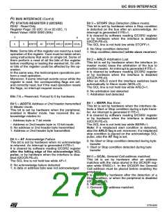
I C STATUS REGISTER 2 (I2CSR2)
Bit 3 = STOPF Stop Detection (Slave mode).
This bit is set by hardware when a Stop condition
is detected on the bus after an acknowledge. An
interrupt is generated if ITE=1.
R242 - Read Only
Register Page: 20 (I2C_0) or 22 (I2C_1)
Reset Value: 0000 0000 (00h)
It is cleared by software reading I2CSR2 register
or by hardware when the interface is disabled
(I2CCR.PE=0).
7
0
0
0
ADDTX AF STOPF ARLO BERR GCAL
The SCL line is not held low while STOPF=1.
0: No Stop condition detected
Note: Some bits of this register are reset by a read
operation of the register. Care must be taken when
using instructions that work on single bit. Some of
them perform a read of all the bits of the register
before modifying or testing the wanted bit. So oth-
er bits of the register could be affected by the op-
eration.
In the same way, the test/compare operations per-
form a read operation.
Moreover, if some interrupt events occur while the
register is read, the corresponding flags are set,
and correctly read, but if the read operation resets
the flags, no interrupt request occurs.
1: Stop condition detected (while slave receiver)
Bit 2 = ARLO Arbitration Lost.
This bit is set by hardware when the interface (in
master mode) loses the arbitration of the bus to
another master. An interrupt is generated if ITE=1.
It is cleared by software reading I2CSR2 register
or by hardware when the interface is disabled
(I2CCR.PE=0).
After an ARLO event the interface switches back
automatically to Slave mode (M/SL=0).
The SCL line is not held low while ARLO=1.
0: No arbitration lost detected
1: Arbitration lost detected
Bits 7:6 = Reserved. Forced to 0 by hardware.
Bit 1 = BERR Bus Error.
Bit 5 = ADDTX Address or 2nd header transmitted
in Master mode.
This bit is set by hardware when the peripheral,
enabled in Master mode, has received the ac-
knowledge relative to:
This bit is set by hardware when the interface de-
tects a Start or Stop condition during a byte trans-
fer. An interrupt is generated if ITE=1.
It is cleared by software reading I2CSR2 register
or by hardware when the interface is disabled
(I2CCR.PE=0).
– Address byte in 7-bit mode
The SCL line is not held low while BERR=1.
Note: If a misplaced start condition is detected,
also the ARLO flag is set; moreover, if a misplaced
stop condition is placed on the acknowledge SCL
pulse, also the AF flag is set.
– Address or 2nd header byte in 10-bit mode.
0: No address or 2nd header byte transmitted
1: Address or 2nd header byte transmitted.
Bit 4 = AF Acknowledge Failure.
0: No Start or Stop condition detected during byte
transfer
1: Start or Stop condition detected during byte
transfer
This bit is set by hardware when no acknowledge
is returned. An interrupt is generated if ITE=1.
It is cleared by software reading I2CSR2 register
after the falling edge of the acknowledge SCL
pulse, or by hardware when the interface is disa-
bled (I2CCR.PE=0).
Bit 0 = GCAL General Call address matched.
This bit is set by hardware after an address
matches with the value stored in the I2CADR reg-
ister while ENGC=1. In the I2CADR the General
Call address must be placed before enabling the
peripheral.
The SCL line is not held low while AF=1.
0: No acknowledge failure detected
1: A data or address byte was not acknowledged
It is cleared by hardware after the detection of a
Stop condition, or when the peripheral is disabled
(I2CCR.PE=0).
0: No match
1: General Call address matched.
275/426
9

 STMICROELECTRONICS [ ST ]