ST92F124/F150/F250 - RESET AND CLOCK CONTROL UNIT (RCCU)
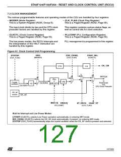
CLOCK MANAGEMENT (Cont’d)
7.3.1 PLL Clock Multiplier Programming
The ST9 being a static machine, there is no lower
limit for INTCLK. However, some peripherals have
their own minimum internal clock frequency limit
below which the functionality is not guaranteed.
The CLOCK1 signal generated by the oscillator
drives a programmable divide-by-two circuit. If the
DIV2 control bit in MODER is set (Reset Condi-
tion), CLOCK2, is equal to CLOCK1 divided by
two; if DIV2 is reset, CLOCK2 is identical to
CLOCK1. Since the input clock to the Clock Multi-
plier circuit requires a 50% duty cycle for correct
PLL operation, the divide by two circuit should be
enabled when a crystal oscillator is used, or when
the external clock generator does not provide a
50% duty cycle. In practice, the divide-by-two is
virtually always used in order to ensure a 50% duty
cycle signal to the PLL multiplier circuit.
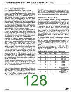
7.3.2 PLL Free Running Mode
The PLL is able to provide a 50-kHz clock, usable
to slow program execution. This mode is
controlled by the FREEN and DX[2:0] bits in the
PLLCONF register: when the PLL is off and the
FREEN bit is set to 1 (i.e. when the FREEN and
DX[2:0] bits are set to 1), the PLL provides this
clock. The selection of this clock is also managed
by the CSU_CKSEL bit but is not conditioned by
the LOCK bit. To avoid unpredictable behaviour of
the PLL clock, Free Running mode must be set
and reset by the user only when the PLL clock is
not the system clock, i.e. when the CSU_CKSEL
bit is reset.
When the PLL is active, it multiplies CLOCK2 by 6,
8, 10 or 14, depending on the status of the MX[0:1]
bits in PLLCONF. The multiplied clock is then di-
vided by a factor in the range 1 to 7, determined by
the status of the DX[0:2] bits; when these bits are
programmed to 111, the PLL is switched off.
In addition, when the PLL provides the internal
clock, if the clock signal disappears (for instance
due to a broken or disconnected resonator...), a
safety clock signal is automatically provided, al-
lowing the ST9 to perform some rescue opera-
tions.
Following a RESET phase, programming bits
DX0-2 to a value different from 111 will turn the
PLL on. After allowing a stabilization period for the
PLL, setting the CSU_CKSEL bit in the
CLK_FLAG Register selects the multiplier clock.
The RCCU contains a frequency comparator be-
tween CLOCK2 and the PLL clock output that ver-
ifies if the PLL reaches the programmed frequency
and has stabilized (locked status). When this con-
dition occurs, the LOCK bit in the CLK_FLAG reg-
ister is set to 1 by hardware and this value is main-
tained as long as the PLL is locked. The LOCK bit
is set back to 0 if for some reason (change of MX
bit value, stop and restart of PLL or CLOCK2,
etc.), the PLL loses the programmed frequency in
which it was locked.
Typ. Safety clock frequency = 800 kHz / Div,
where Div depends on the DX[0..2] bits of the PLL-
CONF register (R246, page55).
Table 26. Free Running Clock Frequency
DX2
0
DX1
0
DX0
0
DIV
2
CK (Typ.)
400 kHz
200 kHz
133 kHz
100 kHz
80 kHz
0
0
1
4
0
1
0
6
0
1
1
8
The PLL selection as system clock is further con-
ditioned by the status of the Voltage Regulator:
when it is not providing a stabilized supply voltage,
the PLL cannot be selected.
1
0
0
10
12
14
1
0
1
67 kHz
1
1
0
57 kHz
50 kHz
1
1
1
1
1
1
16
-
(CSU_CKSEL=0;
FREEN=1)
The maximum frequency allowed for INTCLK is
24 MHz. Care is required, when programming the
PLL multiplier and divider factors, not to exceed
the maximum permissible operating frequency for
INTCLK, according to supply voltage, as reported
in Electrical Characteristics section.
CLOCK2
(CSU_CKSEL=0;
FREEN=0)
128/426
9

 STMICROELECTRONICS [ ST ]